
Crossfire SRT-6 V6-3.2L SC VIN N (2005)
Hydraulic Control Assembly - Antilock Brakes: Description and Operation
HCU (HYDRAULIC CONTROL UNIT)
DESCRIPTION
The CAB (Mark 209 or Mark 259) is a microprocessor based device which monitors the Antilock Brake System (ABS), and the Electronic Stability
Program (ESP) during normal braking and driving functions. The CAB controls brake pressure when the vehicle is in an ABS stop, or if the vehicle is
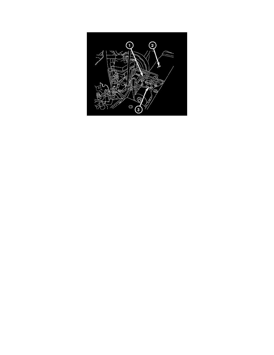
in a spin. The CAB is mounted to the Hydraulic Control Unit (HCU) (3) as part of the Integrated Control Unit (ICU). The CAB uses a 47-way
electrical connector on the vehicle wiring harness. The power source for the CAB is through the 50 amp fuse located in the Engine Fuse Block (2).
OPERATION
All switching components of the ABS system are combined in the ABS hydraulic unit. A 2/2-way valve for build-up/ hold pressure or hold/reduce
pressure functions is used on each wheel for control. At the rear, the same valves are used for both wheels. The return pump integrated in the hydraulic
unit is used to return the brake fluid during the pressure reduction phase.
An increase in pressure compared to the pressure controlled by the master brake cylinder is not possible during the ABS control phase. A muffler is
fitted for each brake circuit to reduce delivery noise. During the ABS pressure reduction phase, the brake fluid flows back to the return pumps via the
low-pressure accumulators.
NORMAL BRAKING FUNCTION
When the driver is applying the brake pedal during a no wheel spin or slip situation, the vehicle builds pressure in the brake hydraulic system to
engage the brakes and stop the vehicle. The hydraulic shuttle valve internal to the ICU closes with every brake pedal application so pressure is not
created at the inlet to the pump/motor and the vehicle stops normally.
ABS BRAKING FUNCTION
During a stop where one wheel is slipping because the driver is attempting to stop the vehicle at a faster rate than is allowed by the surface on which
the tires are riding, the hydraulic shuttle valve closes upon brake application so that the pump/motor cannot siphon brake fluid from the master
cylinder. The normally open and normally closed valves modulate (build/decay) the brake hydraulic pressure as required. The pump/motor is switched
on so that the brake fluid from the low pressure accumulators is returned to the master cylinder circuits. The brake fluid is routed to either the master
cylinder or the wheel brake, depending on the position of the normally open valve.
ABSTRACTION CONTROL FUNCTION
The vehicle in the traction control TC (ASR) mode. If the drive wheel is spinning and brake pressure is required to reduce its speed. The normally
open TC (ASR) valve is energized to isolate the brake fluid being pumped from the master cylinder and to isolate the driven wheel. The normally open
TC (ASR) valve bypasses the pump output back to the master cylinder at a fixed pressure setting. The normally open and normally closed valves
modulate (build/ decay) the brake pressure as required to slow the spinning wheel.