
Crossfire SRT-6 V6-3.2L SC VIN N (2005)
this limit.
Measure rotor thickness at the center of the brake pad contact surface. Replace the rotor if worn below the minimum thickness, or if refinishing would
reduce thickness below the allowable limit.
FRONT ROTOR THICKNESS VARIATION
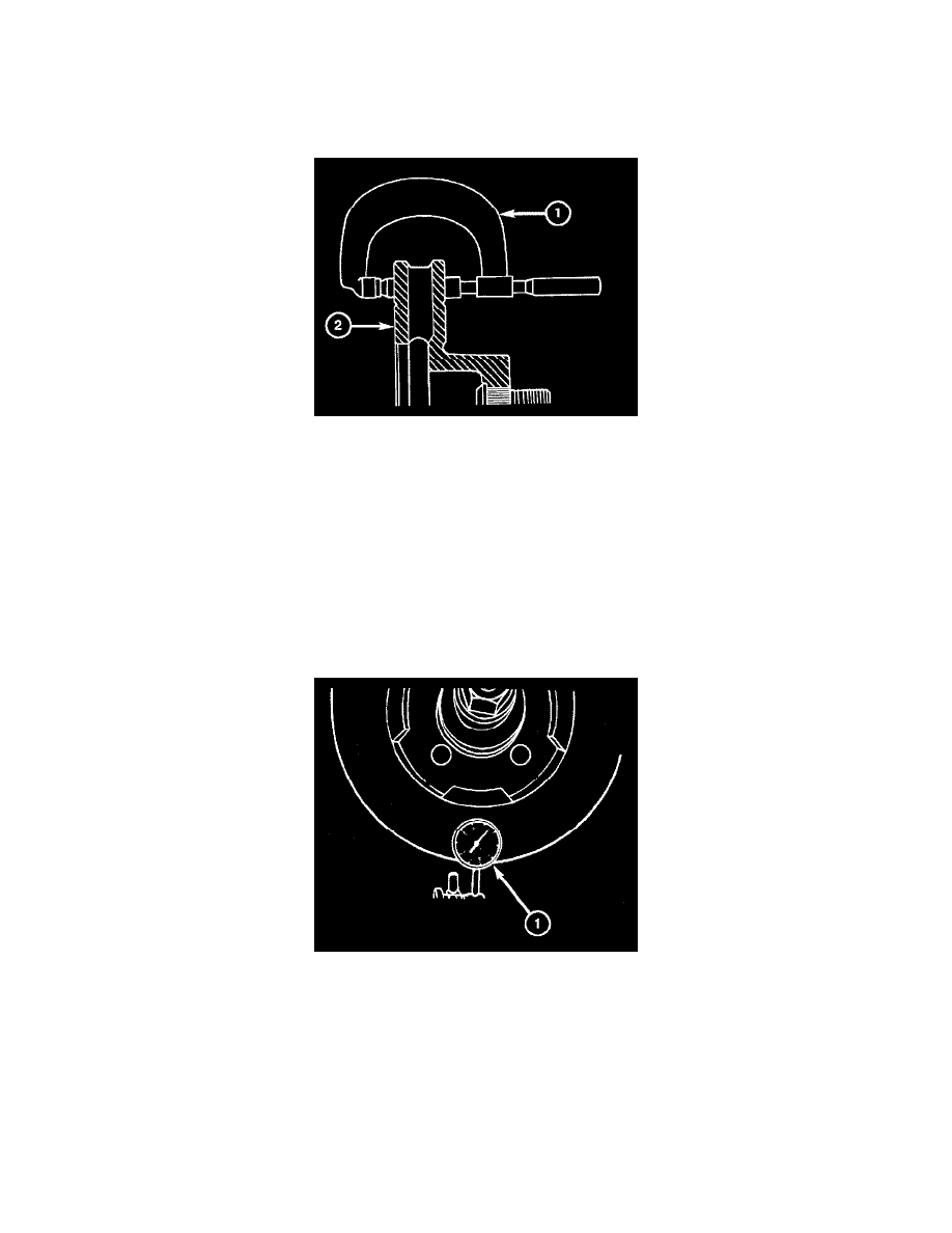
Variations in rotor thickness will cause pedal pulsation, noise and shudder.
Measure rotor (2) thickness a minimum of six points around the rotor face with a micrometer (1). Position the micrometer approximately ¾ inch (19
mm) from the rotor outer circumference for each measurement.
Thickness should not vary by more than 0.0005 inch (0.0127 mm) from point to point on the rotor. Refinish or replace the rotor if necessary.
Note: A hub mounted on-vehicle lathe is recommended. This type of lathe trues; the rotor to the vehicles hub/bearing.
Front rotors and hub/bearings are matched mounted for minimum lateral runout. Before removing the rotor, mark the rotor and hub/bearing to
maintain original orientation.
FRONT ROTOR LATERAL RUNOUT
Check rotor lateral runout whenever pedal pulsation, or rapid, uneven brake lining wear has occurred.
The rotor must be securely clamped to the hub to ensure an accurate runout measurement. Secure the rotor with a minimum of 3 lug nuts and large
diameter flat washers on each stud.
Use a dial indicator (1) to check lateral runout.
Maximum allowable rotor lateral runout is 0.002 inch (0.05 mm).