
Crossfire SRT-6 V6-3.2L SC VIN N (2005)
-
PULSE MODULE
For a complete Powertrain Control Module Circuit Diagram, (Refer to ENGINE SCHEMATICS AND DIAGRAMS).
Diagnostic Test
1. PRE-DIAGNOSTIC CHECK OUT
Note: Always perform diagnostics with a fully charged battery.
Note: Check connectors - Clean/repair as necessary. Poor pin to terminal connections can set DTCs.
Note: Check for applicable TSBs related to the problem. Turn the ignition on. With the DRBIII, read PCM DTCs. Using the wiring
diagram/schematic as a guide, inspect the wiring and connectors. Repair as necessary. Perform this procedure prior to symptom diagnosis.
Continue
Go To 2
2. INSPECT FUSE 13
Note: If there are any Charge Air Cooler Circulation Pump DTCs present, diagnose the DTC(s) before continuing. Turn the ignition off. Remove and
inspect Fuse 13 from the Underhood Accessory Fuse Block.
Is the fuse good?
Yes >> Go To 3
No >> Go To 8
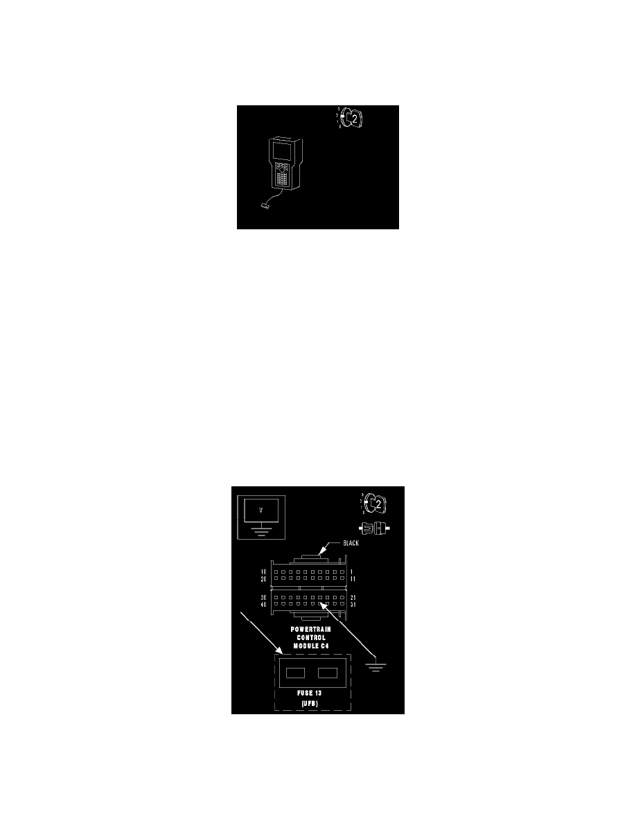
3. MEASURE THE VOLTAGE OF THE CHARGE AIR COOLER CIRCULATION PUMP DRIVER CIRCUIT AT FUSE 13
With the ignition off. Disconnect the PCM C4 harness connector.
Note: Check connectors - Clean/repair as necessary.
Connect a jumper wire between ground and PCM C4 harness connector cavity 34.
Turn the ignition on.