
Crossfire SRT-6 V6-3.2L SC VIN N (2005)
Oxygen Sensor: Description and Operation
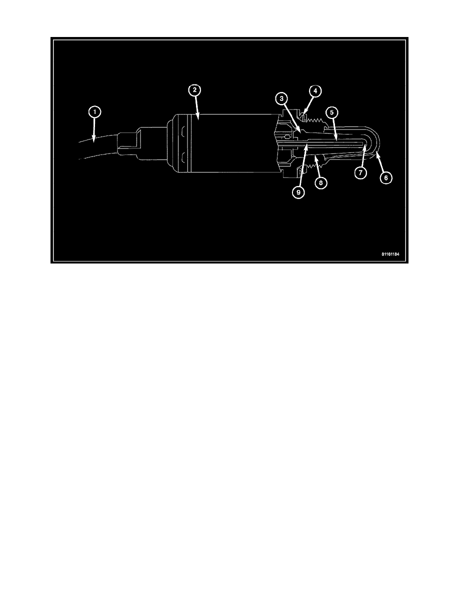
The Oxygen Sensors (O2S) are attached to, and protrude into the vehicle exhaust system. The vehicle uses a total of 4 sensors; 2 upstream (referred to as
1/1 and 2/1) and 2 downstream (referred to as 1/2 and 2/2). The right upstream sensor (1/1) is located in the right exhaust pipe just before the
mini-catalytic converter. The left upstream sensor (2/1) is located in the left exhaust pipe just before the mini-catalytic converter. The right downstream
sensor (1/2) is located in the right exhaust downpipe just after the mini-catalytic converter, and before the main catalytic converter. The left downstream
sensor (2/2) is located in the left exhaust downpipe just after the mini-catalytic converter, and before the main catalytic converter.
An O2 Sensor is a galvanic battery that provides the Powertrain Control Module (PCM) with a voltage signal (0-1 Volt) inversely proportional to the
amount of oxygen in the exhaust. In other words if the oxygen content is low, the voltage output is high; if the oxygen content is high, the voltage output
is low. The PCM uses this information to adjust injector pulse-width to achieve the 14.7 to 1 air/fuel ratio necessary for proper engine operation and to
control emissions. The O2 Sensor must have a source of oxygen outside the exhaust stream for comparison. Current O2 Sensors receive their fresh
oxygen (outside air) supply through the O2 Sensor case housing. Four wires (circuits) are used on each O2 Sensor: a 12-Volt feed circuit for the sensor
heating element, a ground circuit for the heater element, a low-noise sensor return circuit to the PCM and an input circuit from the sensor back to the
PCM to detect sensor operation.
As vehicles accumulate mileage, the catalytic convertor deteriorates. The deterioration results in a less efficient catalyst. To monitor catalytic convertor
deterioration, the fuel injection system uses two heated oxygen sensors. One sensor upstream of the catalytic convertor, one downstream of the convertor.
The PCM compares the reading from the sensors to calculate the catalytic convertor oxygen storage capacity and converter efficiency. Also, the PCM
uses the upstream heated oxygen sensor input when adjusting injector pulse width.
When the catalytic converter efficiency drops below emission standards, the PCM stores a Diagnostic Trouble Code (DTC) and illuminates the
Malfunction Indicator Lamp (MIL).
The O2 Sensors produce voltages from 0 to 1 volt, depending upon the oxygen content of the exhaust gas. When a large amount of oxygen is present
(caused by a lean air/fuel mixture, can be caused by misfire and exhaust leaks), the sensors produces a low voltage. When there is a lesser amount of
oxygen present (caused by a rich air/fuel mixture, can be caused by internal engine problems) it produces a higher voltage. By monitoring the oxygen
content and converting it to electrical voltage, the sensors act as a rich-lean switch.
The O2 Sensors are equipped with a heating element that keeps the sensors at proper operating temperature during all operating modes. Maintaining
correct sensor temperature at all times allows the system to enter into closed loop operation sooner. Also, it allows the system to remain in closed loop
operation during periods of extended idle. In Closed Loop operation the PCM monitors the O2 Sensors input (along with other inputs) and adjusts the
injector pulse width accordingly. During Open Loop operation the PCM ignores the O2 Sensor input. The PCM adjusts injector pulse width based on
preprogrammed (fixed) values and inputs from other sensors.
The Engine Control Relay located in the Relay Control Module supplies battery voltage to both the upstream and downstream heated O2 Sensors. The
O2 Sensors are equipped with a heating element. The heating elements reduce the time required for the sensors to reach operating temperature. The PCM