
Crossfire SRT-6 V6-3.2L SC VIN N (2005)
Body Control Module: Description and Operation
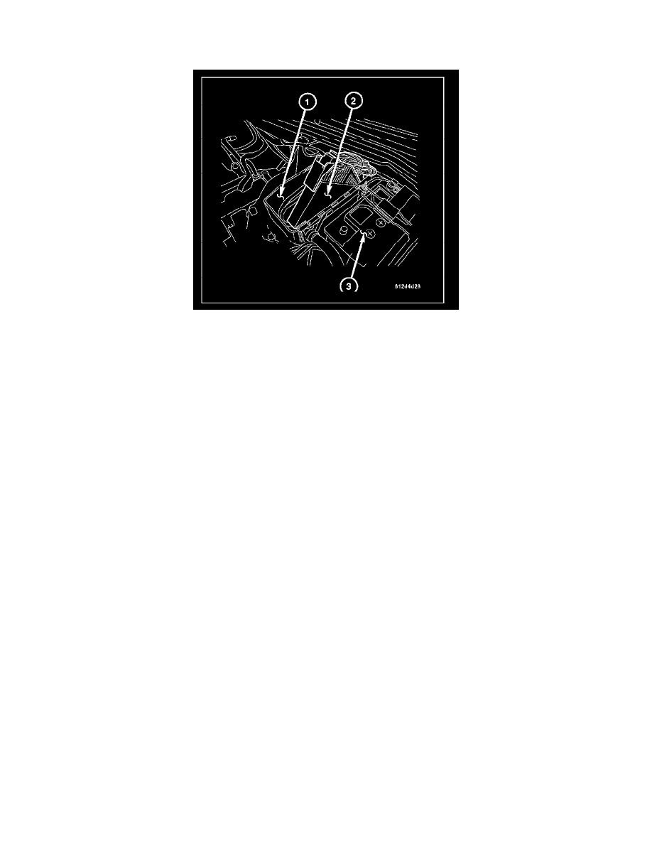
Description-RHD
The Body Control Module (BCM) (2) is concealed in the engine compartment inside of the Control Module Box (1) located next to the battery (3).
The BCM utilizes integrated circuitry and information carried on the Controller Area Network (CAN) bus along with many hardwired inputs to monitor
many sensor and switch inputs throughout the vehicle. In response to those inputs, the internal circuitry and programming of the BCM allows it to control
and integrate many electronic functions and features of the vehicle through both hardwired outputs and the transmission of electronic message outputs to
other electronic modules in the vehicle over the CAN data bus.
The BCM for this model is serviced only as a complete unit. A BCM can only be repaired by or replaced through an authorized electronic warranty
repair station. Refer to the latest version of the Warranty Policies and Procedures manual for a current listing of authorized electronic repair stations.
CONTROL MODULE COOLING FAN
A Control Module Cooling Fan is located inside of the front lower section of the Control Module Box (1). The Cooling Fan is wired to the BCM and is
switched on when the ignition is On. The Cooling Fan is attached to a duct which pulls cabin temperature air from the passenger compartment and
circulates it into the Control Module Box in order to decrease the heat that may be generated by the Powertrain Control Module (PCM), the BCM, and
the Relay Control Module.
The Body Control Module is designed to control and integrate many of the electronic features and functions of the vehicle. The microprocessor-based
Body Control Module hardware and software monitors many hardwired switch and sensor inputs as well as those resources it shares with other electronic
modules in the vehicle through its communication over the Controller Area Network (CAN) Bus. The internal programming of the Body Control Module
microprocessor allows the Body Control Module to determine the tasks it needs to perform and their priorities. The Body Control Module programming
then performs those tasks and provides features through both CAN Bus communication with other electronic modules and hardwired outputs to a number
of relays. These relays provide the Body Control Module with the ability to control numerous high current accessory systems in the vehicle.
The Body Control Module circuitry operates on battery current received through fuses in the Underhood Accessory Fuse Block on a non-switched fused
B(+) circuit, a fused ignition switch output (start-on/run) circuit, and a fused ignition switch output (start-on/run-accessory) circuit. This arrangement
allows the Body Control Module to provide some features regardless of the ignition switch position. The Body Control Module circuitry is grounded
through the chassis behind the right side lower A-pillar kick panel.
The Body Control Module monitors its own internal circuitry as well as many of its input and output circuits and will store a Diagnostic Trouble Code
(DTC) in electronic memory for any failure it detects. These DTCs can be retrieved and diagnosed using a DRB III(R) scan tool.