
Fifth Avenue V6-231 3.8L VIN L FI (1992)
Radiator Cooling Fan Motor: Testing and Inspection
Motor Circuit Testing
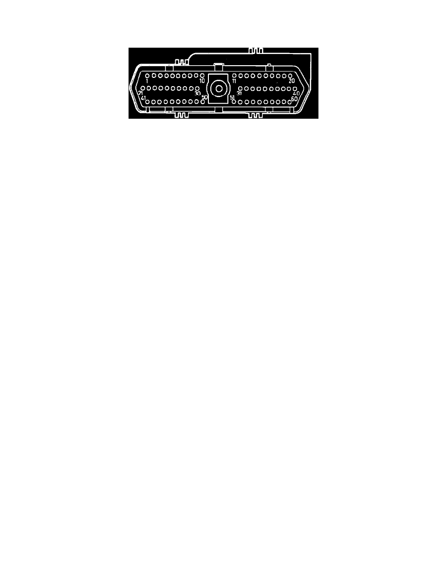
Fig. 37 Engine Controller 60-way Connector
1. Run engine at normal operating temperature.
2. Check wiring connector in C25, C9 and C26 for proper engagement.
3. Connect DRB II or equivalent scan tool to vehicle and check for fault codes.
4. If fault code 88,12,35, or 55 is detected, proceed to step 5.
5. With ignition in RUN position, test for battery voltage at fan relay single pin connector. If battery voltage is detected, proceed to step 7.
6. If voltage reads at zero to one volt, proceed to step 7.
7. With ignition switch in OFF position, disconnect the 60-way connector from engine controller and return ignition switch to RUN position. Test for
battery voltage at terminal 31 of 60-way connector. If battery voltage is present and female terminal is not damaged, replace engine controller. If
battery voltage is not present, repair open or short in circuit C27.
8. With ignition switch in OFF position, disconnect 60-way connector from engine controller and return ignition switch to RUN position. Test for
battery voltage at single pin connector on fan relay. If battery voltage exists, replace engine controller. If voltage is zero to one volt proceed to step
9.
9. With ignition switch in RUN position, test for battery voltage at wire C27 in 3-way connector of fan relay. If battery voltage exists, replace fan
relay. If voltage is zero to one, repair open or short in circuit C27.
10. Turn ignition switch OFF, connect 60-way connector and test system.