
Fifth Avenue V6-231 3.8L VIN L FI (1992)
Camshaft Position Sensor: Description and Operation
Camshaft Sensor
Location
Sensor mounted in top of timing case cover above cam sprocket.
Purpose
^ Sensor provides PCM with cylinder identification.
^ PCM uses sensor input to determine fuel injection sequence and ignition timing.
Operation
Sensor generates pulses as groups of notches on the camshaft sprocket pass underneath it.
^ When metal aligns with the sensor, voltage goes low (less than 0.3 volts).
^ When a notch aligns with the sensor, voltage spikes high (5.0 volts).
^ As a group of notches pass under the sensor, the voltage switches from low (metal) to high (notch) then back to low.
^ The number of notches determine the amount of pulses.
Note:
If available, an oscilloscope can display the square wave patterns of each timing event.
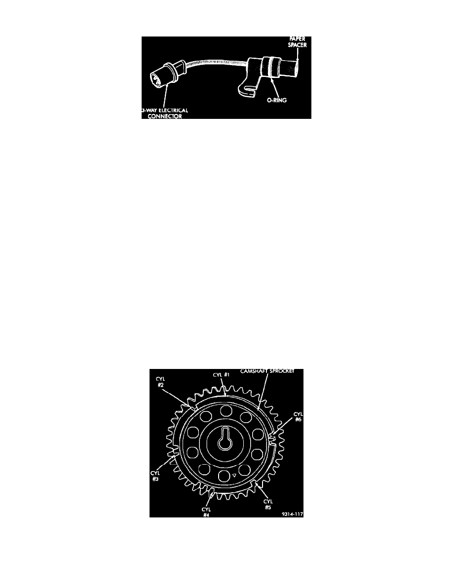
Note:
The arrows and cylinder call outs on the following image represent which cylinder the flat spot and notches identify, they do not indicate TDC
position.
Camshaft Sprocket
^ When the PCM receives two cam pulses followed by the long flat spot on the camshaft sprocket, it knows that the crankshaft timing marks for
cylinder # 1 are next (on driveplate).