
LeBaron L4-135 2.2L VIN B 2-bbl (1982)
Install the yellow wire just removed from bulkhead connector into the loose natural colored 1-way connector supplied in the instrument panel
overlay harness, PN 4368642.
4.
Insert two bare terminals on instrument panel overlay harness, PN 4368642, into the instrument panel side of the bulkhead connector (Figure
2-D) as follows:
a.
Yellow wire into cavity #30.
b.
Gray with black tracer wire into cavity #9.
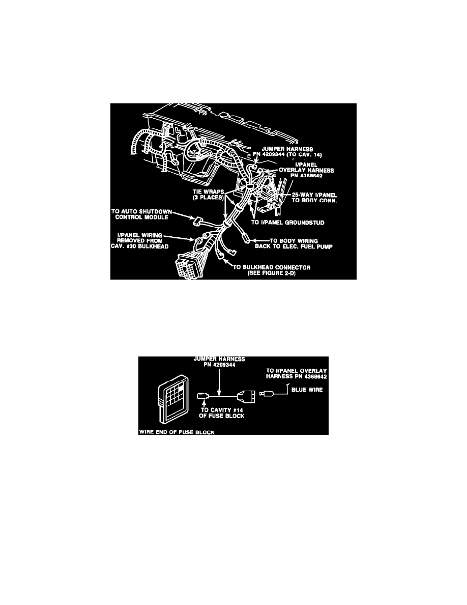
FIGURE 2-A - INSTRUMENT PANEL WIRING
5.
Connect the natural colored 1-way connector (on overlay harness, PN 4368642) to the loose natural colored 1-way connector that was
installed on the wire removed from cavity #30 of the instrument panel side of the bulkhead connector in Step 3 (Figure 2-A).
6.
Route instrument panel overlay harness, PN 4368642, along the main instrument panel wiring harness and secure with three tie wraps, PN
6015756 (Figure 2-A).
FIGURE 2-C
7.
Insert the bare terminal (blue wire) from overlay harness, PN 4368642, into wiring jumper harness, PN 4209344. Install the bare terminal
from the jumper harness, PN 4209344, into cavity #14 of the fuse block (Figure 2-C).
NOTE:
SOME 1981-1982 VEHICLES MAY ALREADY BE EQUIPPED WITH JUMPER HARNESS, PN 4209344, IN
CAVITY #14 OF THE FUSE BLOCK. IF SO, DISCARD JUMPER HARNESS, PN 4209344, SUPPLIED IN KIT.
8.
Install 10-amp fuse, PN 6101135, supplied in kit into cavity #14 of the fuse block.
NOTE:
CERTAIN 1981-1982 VEHICLES HAVE A 6-AMP CIRCUIT BREAKER IN CAVITY #14 OF THE FUSE BLOCK.
LEAVE THE CIRCUIT BREAKER IN CAVITY #14 AND DO NOT USE THE SUPPLIED 10-AMP FUSE.
9.
Reinstall passenger compartment side of the bulkhead connector back into dash opening. Be sure it snaps in place.
10.
Install the fuse block onto the mounting bracket.