
Lebaron Convertible L4-135 2.2L SOHC Turbo VIN E FI (1985)
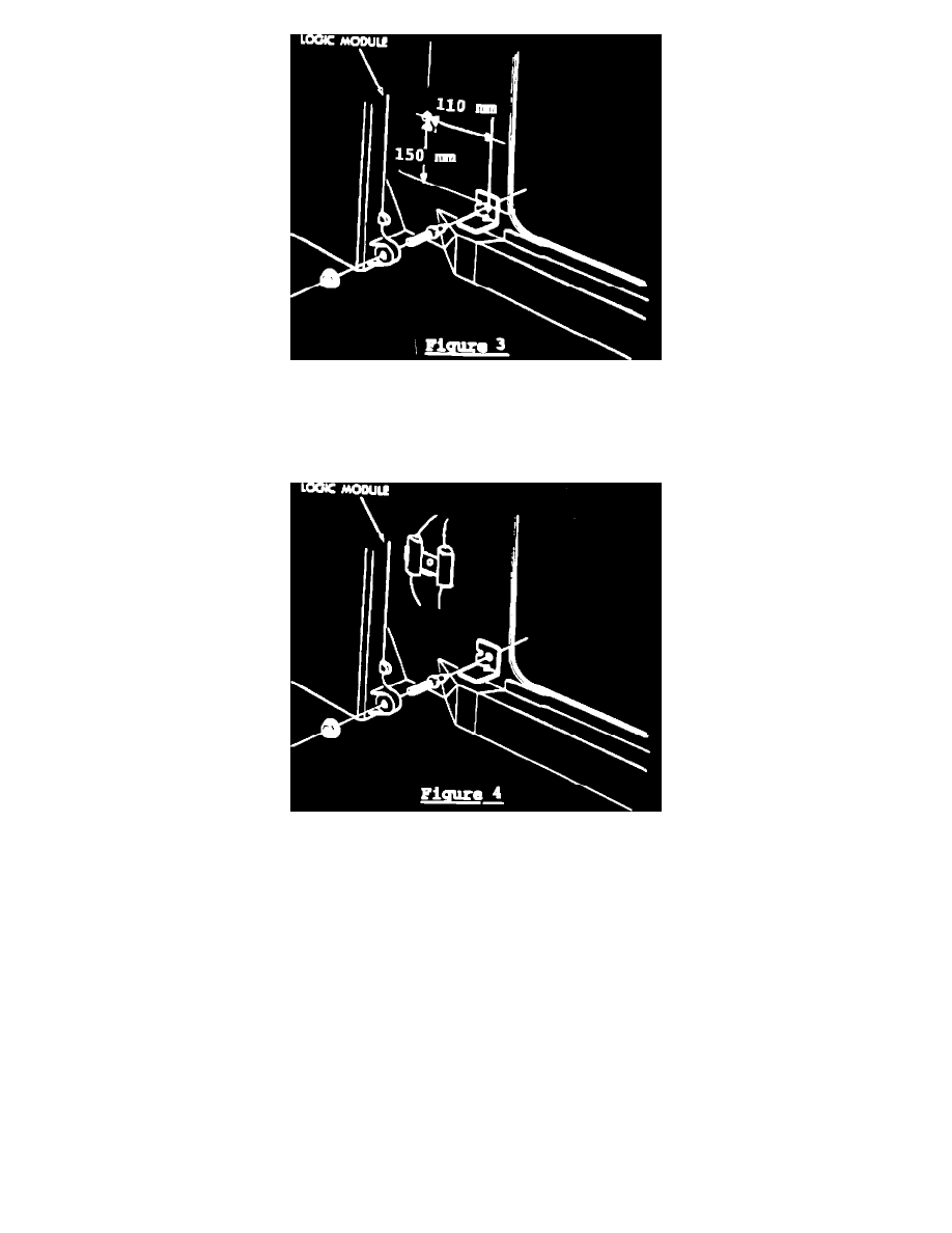
FIGURE 3
5.
Shadow/Sundance Only
a.
Punch or drill (with a #31 drill) a 3 mm hole on the right kick plate area (Figure 3).
FIGURE 4
b.
Align capacitor assembly, PN 4443174, on right side kick area and mount with the self-piercing screw (Figure 4).
c.
Disconnect the existing blower motor pigtail from wiring harness. Then connect the wires from capacitor assembly to connectors from
wiring harness and blower motor.
6.
Install logic module per service manual procedures.
7.
Reinstall glove box assembly.
8.
Reconnect battery.
9.
Verify blower motor operation and perform diagnosis to assure proper installation.
POLICY:
Reimbursable within the provisions of the warranty
TIME ALLOWANCE:
Labor Operation No.
08-60-02-93 . . . . . . . . . . . . .
0.5 Hrs.
FAILURE CODE:
68 - Noisy