
Lebaron Sedan L4-153 2.5L SOHC Turbo VIN J FI (1991)
Camshaft: Service and Repair
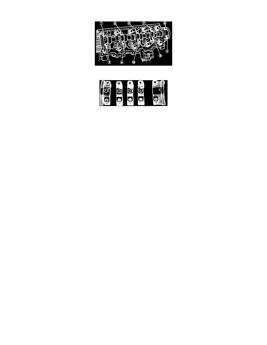
Fig. 36 Camshaft Bearing Cap Removal
Fig. 37 Camshaft Bearing Cap Installation
Removal and installation of camshaft requires separation of camshaft sprocket from camshaft. In order to maintain camshaft, intermediate shaft and
crankshaft timing, the timing belt is left indexed on the camshaft sprocket while the assembly is suspended under light tension, Fig. 36.
When removing camshaft sprocket from camshaft, adequate tension on sprocket and belt assembly must be maintained to prevent the timing belt from
disengaging from the intermediate or crankshaft timing sprockets.
NOTE: Failure to maintain adequate tension on timing belt may result in incorrect engine timing.
1.
Mark rocker arms to ensure installation in original position.
2.
Evenly loosen camshaft bearing bolts in sequence shown in Fig. 36, until all bolts have been loosened 3-4 turns.
3.
Tap rear of camshaft with suitable mallet to break caps free.
4.
Continue loosening bearing cap bolts, ensuring camshaft does not cock, then remove bearing caps and camshaft. Loosen bearing cap bolts evenly.
If camshaft cocks in bearing bores, bearing surfaces may be damaged.
5.
With caps removed from engine, check oil holes for obstructions. Some engines may be equipped with oversize camshaft bearings. Engines with
oversize camshaft bearings can be identified by green markings on cylinder head and camshaft at AIR pump side of engine.
6.
Check camshaft lobe height in center (contact area) and on shoulders of lobe. If difference in reading exceeds .010 inch (.25 mm), camshaft should
be replaced.
7.
Install rocker arms in original positions, then position camshaft in bearing saddles of cylinder head.
8.
Apply suitable sealant to No. 1 and No. 5 bearing cap.
9.
Align caps in proper sequence, with No. 1 cap at timing belt end and No. 5 cap at flywheel end of engine, and ensure arrow on caps 1, 2, 3 and 4
point toward timing belt, Fig. 37. Install caps before installing camshaft seals.
10.
Torque cap bolts to specifications. Torque cap bolts evenly in crossing pattern to ensure camshaft remains properly aligned.
11.
Install camshaft seals as outlined.