
Lebaron Town & Country L4-156 2.6L SOHC VIN G 2-bbl (1984)
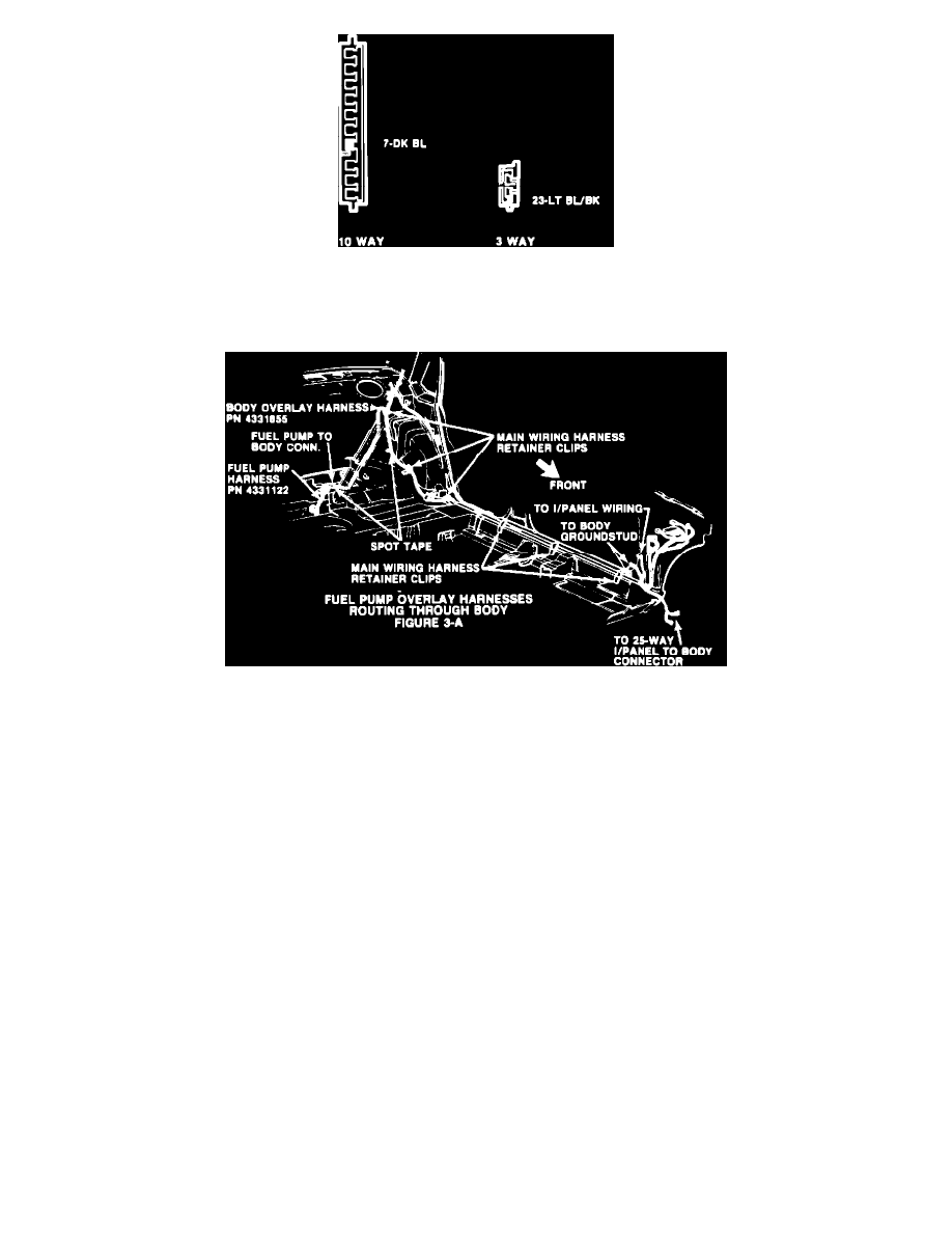
FIGURE 3-F - (TERMINAL END OF WEDGE CONN.)
10.
Insert the 3 and 10-way wedge connectors into the 25-way instrument panel-tobody connector and reinstall the 25-way connector (Figure
3-F).
FIGURE 3-A - FUEL PUMP OVERLAY HARNESSES ROUTING THROUGH BODY
11.
Install the black 2-way connector on the body overlay harness, PN 4331855, to the black 2-way connector on the instrument panel overlay
harness, PN 4331801 (Figure 3-A).
12.
Reinstall the left side sill scuff plate, left side cowl kick panel, spare tire, and upper and lower rear seat cushions.
D.
Engine Compartment
1.
Remove and discard the 90~ formed hose located between the fuel pump outlet and the carburetor inlet (hose between tbe fuel pump outlet
and fuel flow sensor inlet if equipped with fuel flow sensor).
If the vehicle has a fuel reservoir, disconnect the reservoir inlet hose at the pump and the outlet hose at the carburetor (outlet hose at fuel flow
sensor inlet, if equipped with fuel flow sensor). Remove and discard the reservoir and hoses.