
Lebaron Town & Country L4-156 2.6L SOHC VIN G 2-bbl (1984)
Crankshaft Position Sensor: Service and Repair
Disassembly & Assembly
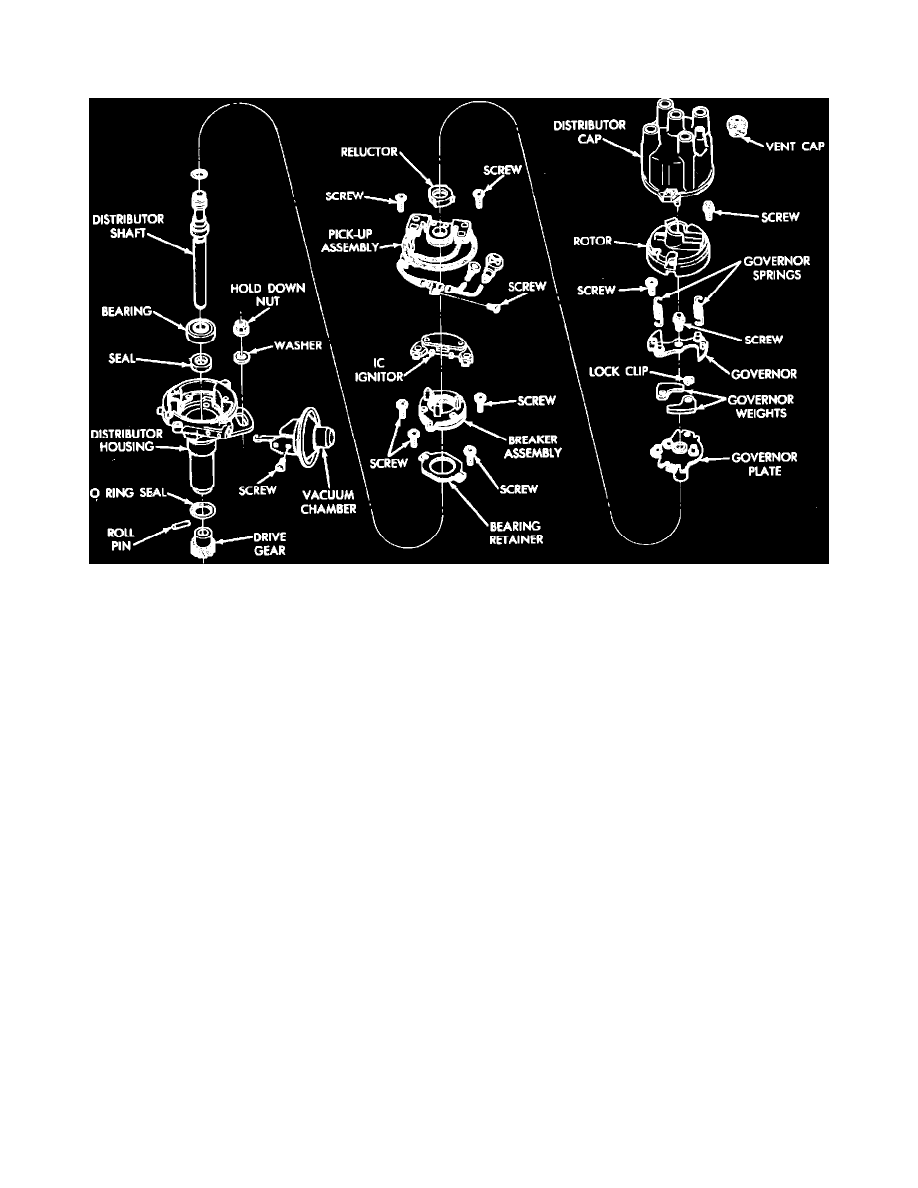
Fig. 1 Disassembled view of electronic ignition distributor
DISASSEMBLY
1.
Remove distributor rotor.
2.
Remove governor assembly retaining screw, Fig. 1, and governor assembly. Governor springs are not interchangeable and must be installed in
their original positions. Note position of each spring during disassembly for reference during assembly.
3.
Remove wire retaining clamp from side of distributor.
4.
Remove pickup coil and ECU igniter retaining screws, then remove pickup coil and ECU igniter as an assembly.
5.
Remove vacuum chamber retaining screws, then the vacuum chamber assembly.
6.
Remove breaker assembly retaining screws, then the breaker assembly.
7.
Remove bearing retainer plate screws, then the bearing retainer plate.
8.
Mark relationship of distributor drive gear to distributor shaft, then punch out distributor drive gear retaining pin and remove gear from shaft.
9.
Remove distributor shaft and bearing assembly from housing.
10.
Remove distributor housing seal.
ASSEMBLY
1.
Lubricate distributor housing seal with suitable grease and install into distributor housing.
2.
Install distributor shaft and bearing assembly into distributor housing.
3.
Install distributor drive gear onto shaft and align marks made during disassembly.
4.
Install drive gear roll pin, then install bearing retainer and retaining screws.
5.
Install breaker assembly and retaining screws.
6.
Install vacuum chamber onto distributor housing and secure with retaining screws.
7.
Install pickup coil and ECU igniter as an assembly into housing, then install retaining screws.
8.
Install wire retaining clamp and governor assembly. If governor assembly was disassembled, check to ensure that governor springs are installed in
original positions.
9.
Install governor assembly retaining screw and rotor.