
LHS V6-3.5L VIN G (1998)
Brake Rotor/Disc: Testing and Inspection
GENERAL INFORMATION
Any servicing of the rotor requires extreme care to maintain the rotor within service tolerances to ensure proper brake action.
Before refinishing or refacing a rotor, the disc should be checked and inspected for the following conditions:
-
Braking surface scoring, rust, impregnation of lining material and worn ridges.
-
Excessive lateral runout or wobble.
-
Thickness variation (Parallelism).
-
Dishing or distortion (Flatness).
If a vehicle has not been driven for a period of time, the rotor surface will rust in the area not covered by the brake lining and cause noise and
chatter when the brakes are applied.
Excessive wear and scoring of the rotor can cause temporary improper lining contact if ridges are not removed before installation of new brake pad
assemblies.
Some discoloration or wear of the rotor surface is normal and does not require resurfacing when linings are replaced.
Excessive runout or wobble in a rotor can increase pedal travel due to piston knock back. This will increase guide pin bushing wear due to
tendency of caliper to follow rotor wobble.
Thickness variation in a rotor can also result in pedal pulsation, chatter and surge due to variation in brake output. This can also be caused by
excessive runout in rotor or hub.
Dishing or distortion can be caused by extreme heat and abuse of the brakes.
ROTOR RUNOUT AND THICKNESS VARIATION
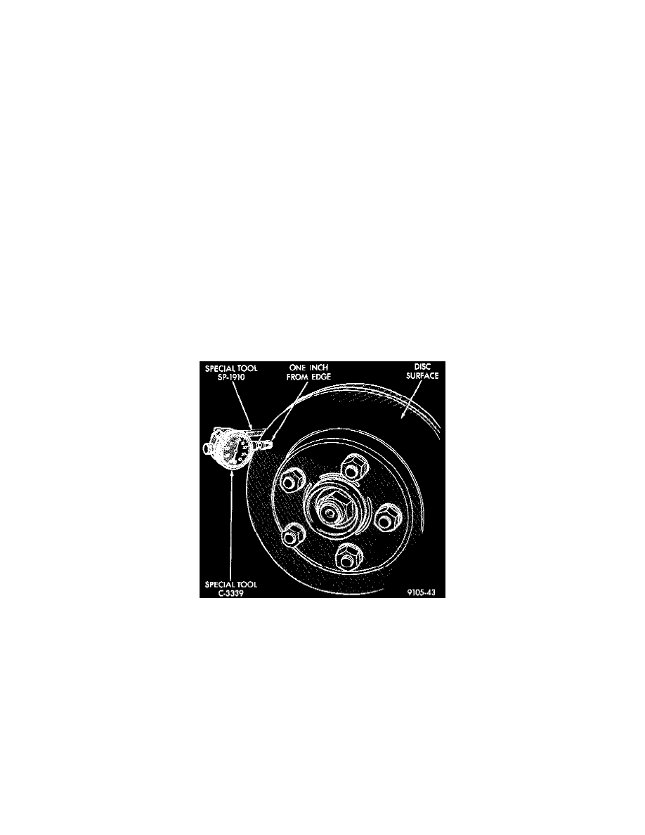
Checking Rotor For Runout
On vehicle rotor runout is the combination of the individual runout of the hub face and the runout of the rotor. (The hub and rotor run-outs are
separable). To measure runout on the vehicle, remove the wheel and reinstall the lug nuts tightening the rotor to the hub. Mount Dial Indicator,
Special Tool C-3339 with Mounting Adaptor, Special Tool SP-1910 or equivalents on steering arm. Dial indicator plunger should contact braking
surface of rotor approximately one inch from edge of rotor. Check lateral runout (both sides of rotor) runout should not exceed 0.09 mm (0.0035
inch).