
LHS V6-3.5L VIN G (1998)
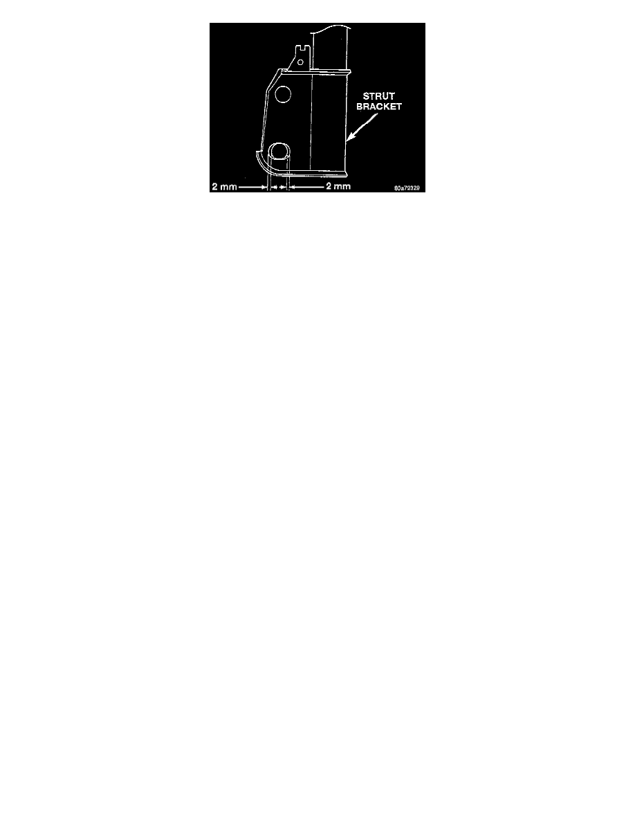
CAUTION: When grinding the bottom mounting hole in the strut to create the slot, do not enlarge the hole more then 2 mm in either direction as
shown if the strut is not marked to show the shape of the slot.
9. Using an appropriate grinder and cutting tool, slot the bottom hole in both sides of the strut clevis bracket. When grinding slot do not go beyond
the indentation area on the sides of the clevis bracket.
10. Install the steering knuckle in the strut bracket.
11. Loosely install the bolts attaching the strut to the steering knuckle.
12. If removed, install the routing bracket for the wheel speed sensor on the strut.
13. Install outer tie rod on strut. Install outer tie rod attaching nut. Tighten the tie rod attaching nut to a torque 37 Nm (27 ft. lbs.).
14. Install stabilizer bar attaching link on strut. Tighten the stabilizer bar attaching link nut to a torque of 88 Nm (65 ft. lbs.).
15. Install the wheel and tire assemblies.
16. Lower vehicle until the full weight of the vehicle is supported by the vehicles, suspension.
17. Correctly jounce the front and rear of vehicle an equal amount of times.
18. Adjust the front camber to the preferred setting by pushing in or pulling outward on the top of the wheel and tire as required. When camber is
correctly set, tighten the upper and lower attaching bolt enough to not allow the steering knuckle to move in the strut bracket. Again jounce front
and rear of vehicle an equal amount of times and verify front camber setting. See Alignment Specifications.
19. When front camber is correctly set, torque both front strut clevis to steering knuckle attaching bolts to 203 Nm (150 ft. lbs.).
20. Check the front wheel Toe settings. If Toe readings obtained are not within the required specification range, adjust Toe to meet the preferred
specification setting. Adjust front Toe to the preferred the Toe specification using the Toe setting procedure.
21. Road test the vehicle. If vehicle still drifts or leads, repeat the camber adjustment procedure but bias the cross car camber setting opposite of the
direction in which the vehicle has the tendency to lead. For example, if the vehicle leads left, compensate by setting left front camber to 0.0
degrees and right front camber to +0.6 degrees. The cross car camber is now at +0.6 degrees, the maximum allowed per the alignment
specification.