
LHS V6-3.5L VIN G (1998)
Strut Assembly Mounting
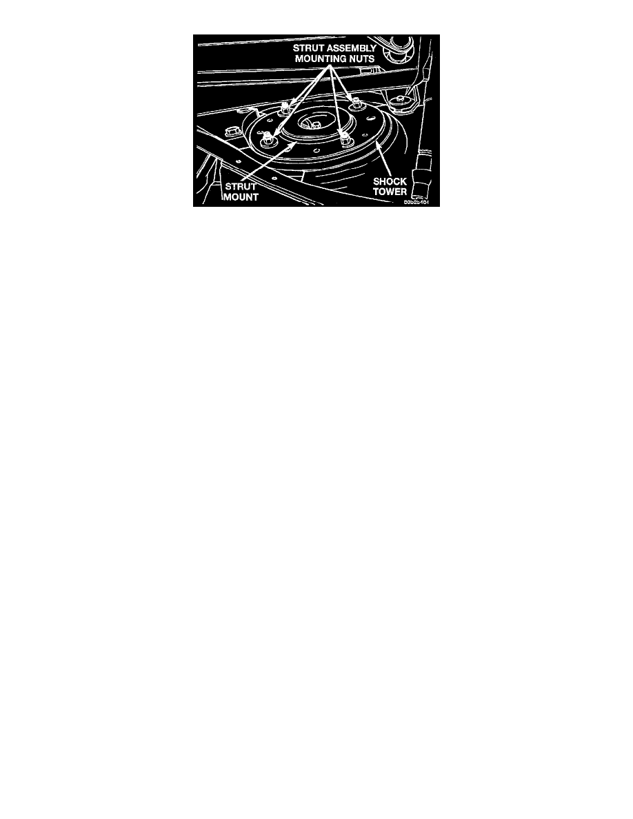
9. Remove the 4 strut assembly upper mount to strut tower mounting nut and washer assemblies.
10. Remove the strut assembly from the vehicle for inspection and or disassembly.
INSTALL
1. Install front strut assembly into shock tower. Install the 4 strut assembly upper mount to shock tower attaching nuts. Tighten the 4 strut mount to
strut tower attaching nuts to a torque of 37 Nm (28 ft. lbs.) torque.
2. Position steering knuckle into strut assembly.
CAUTION: The strut assembly to steering knuckle bolts are serrated were they go through strut assembly and steering knuckle. When installing
bolts, turn nuts onto bolts DO NOT TURN BOLTS IN STEERING KNUCKLE. If bolts are turned damage to steering knuckle will result.
3. Install the strut assembly to steering knuckle attaching bolts. Install nuts on attaching bolts. Tighten the strut assembly clevis to steering knuckle
attaching bolt nuts to a torque of 203 Nm (150 ft. lbs.).
4. Install braking disc back on front hub and bearing assembly. Install front brake caliper assembly on steering knuckle. Install the 2 caliper assembly
to steering knuckle attaching bolts. Tighten the caliper assembly guide pin bolts to a torque of 19 Nm (192 inch lbs.).
5. If the vehicle is equipped with antilock brakes. Install the front speed sensor cable routing bracket onto the front strut assembly.
6. Install outer tie rod on strut assembly. Install tie rod attaching nut. Tighten the tie rod attaching nut to a torque of 37 Nm (27 ft. lbs.).
7. Install stabilizer bar link on strut. Tighten the stabilizer link attaching nut to a torque of 95 Nm (70 ft. lbs.).
8. Install the wheel and tire assembly.
9. Tighten the wheel mounting nuts in proper sequence until all nuts are torqued to half specification. Then repeat the tightening sequence to the full
specified torque of 129 Nm (95 ft. lbs.).
10. Lower vehicle.
Removal
NOTE: When removing rear strut assembly from vehicle, access for the 3 rear strut assembly to strut tower attaching nuts is through the passenger
compartment of the vehicle.
1. Remove the rear seat cushion from the interior of the car. Refer to Body and Frame for the required procedure to be used for this vehicle.
2. Remove the rear seat back assembly. Refer to Body and Frame for the required procedure to be used for this vehicle.
3. Remove both upper quarter trim panels from the rear of the vehicle interior. Refer to Body and Frame for the required procedure to be used for
this vehicle.
4. Remove both lower quarter trim panels from the rear of the vehicle interior. Refer to Body and Frame for the required procedure to be used for this
vehicle.
5. Remove the rear parcel shelf trim panel from the vehicle interior. Refer to Body and Frame for the required procedure to be used for this vehicle.
Remove the 4 screws securing the rear speaker and mounting plate in place for the side of the vehicle requiring repair. The speaker should be
removed from the vehicle with the mounting plate attached. Unplug the wiring from the speaker, then remove the speaker and mounting plate from
the vehicle.
6. Raise vehicle on jack stands or centered on a frame contact type hoist.
7. Remove the rear wheel and tire assembly from the vehicle.