
New Yorker V6-181 2972cc 3.0L SOHC VIN 3 FI (1989)
ABS Pump: Description and Operation
The ABS system uses a pump/motor assembly which is mounted to a transaxle bracket on the left side of the engine compartment below the hydraulic
assembly. The pump/motor takes low pressure fluid from the hydraulic assembly fluid reservoir through the return hose and returns it at high pressure to
the accumulator through the high pressure hose. Rubber isolators are used in mounting the pump to the bracket for noise isolation.
The pump/motor is serviceable as an entire assembly. Hoses are also serviceable as an assembly.
The Pressure Monitoring Module is calibrated to turn the pump motor on at an accumulator pressure of approximately 2100 psi and to turn the
pump/motor off at approximately 2600 psi.
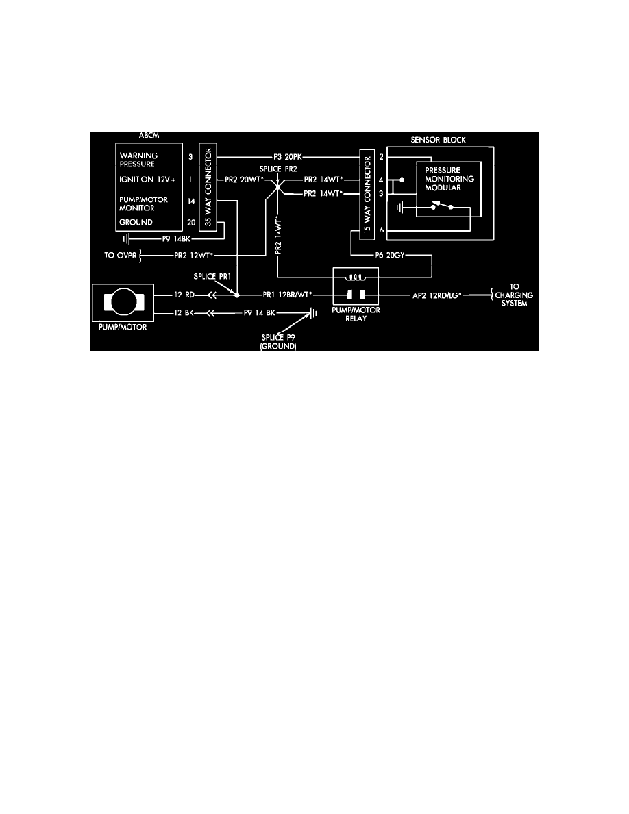
Pump/Motor Circuit
CIRCUIT OPERATION
The pump/motor relay coil is provided power at key-on through the over-voltage protection relay. The coil ground line circuit P6 20GY is held at 12
volts at all times with the ignition on. When pump operation is desired, the Pressure Monitoring Module grounds the relay coil at Sensor Block pin 6.
Power is supplied to the pump/motor through fusible link circuit AP1-20GY. The pump/motor ground circuit is provided directly through circuit
P9-14BK at splice P9.
A pump/motor monitoring line (circuit PR1-14BR/WT) runs from the pump/motor relay to ABCM connector pin 14. This circuit is not used by the
ABCM and is included in the harness for testing purposes only.
NOTE: Pump/motor operation is controlled by the Pressure Monitoring Module in the Hydraulic Assembly Sensor Block and not the ABCM.