
New Yorker V6-3.5L VIN F (1994)
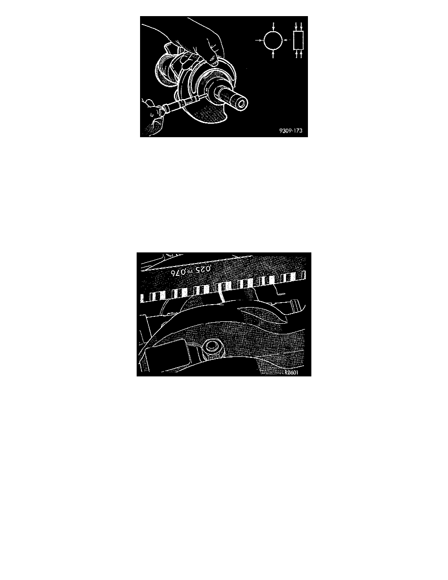
1. Measure the journal outside diameter as shown in the illustration. Refer to Crankshaft Specifications.
NOTE: The crankshaft journals should be checked for excessive wear, taper and scoring. Limits of taper or out-of-round on any crankshaft journals
should be held to 0.025 mm (0.001 inch). Journal grinding should not exceed 0.305 mm (0.012 inch) under the standard journal diameter. DO NOT
grind thrust faces of Number 2 main bearing. DO NOT nick crank pin or bearing fillets. After grinding, remove rough edges from crankshaft oil holes
and clean out all passages.
CAUTION: Forged steel crankshafts require that the final paper or cloth polish after any journal regrind be in the same direction as normal rotation in
the engine.
2. Remove oil from journal and bearing shell.
3. Install crankshaft.
4. Cut plastigage to same length as width of the bearing and place it in parallel with the journal axis.
5. Install the main bearing cap carefully and tighten the bolts to specified torque.
CAUTION: Do not rotate crankshaft or the plastigage will be smeared.
6. Carefully remove the bearing cap and measure the width of the plastigage at the widest part using the scale on the plastigage package. Refer to
Crankshaft Specifications for proper clearances. If the clearance exceeds the specified limits. Replace the main bearing(s) and if necessary have the
crankshaft machined to next undersize. Also see Measuring Main and Connecting Rod Bearing Clearance in Standard Service Procedures.
Measuring Main Bearing Clearance
PLASTIGAGE METHOD
Engine crankshaft bearing clearances can be determined by use of Plastigage or equivalent. The following is the recommended procedure for the
use of Plastigage:
NOTE: The total clearance of the main bearings can only be determined by removing the weight of the crankshaft. This can be accomplished by
either of two methods:
Preferred Method
Shimming the bearings adjacent to the bearing to be checked in order to remove the clearance between upper bearing shell and the crankshaft. This
can be accomplished by placing a minimum of 0.254 mm (0.010 inch) shim (e.g. cardboard, match-book cover, etc.) between the bearing shell
and the bearing cap on the adjacent bearings and tightening bolts to 14 - 20 Nm (10 - 15 ft. lbs.). The number of main bearing will vary from