
Pacifica V6-3.8L (2008)
SPECIAL TOOLS/EQUIPMENT REQUIRED:
IPM CONNECTOR REPAIR PROCEDURE:
1.
Replace the spread terminal in cavity 15 as follows:
2.
Disassemble the C8 connector in order to remove the female terminal from cavity 15.
3.
Cut the spread terminal off of the body wiring harness allowing enough wire length to solder the new wire jumper, provided in the kit, onto the
wiring harness.
4.
Remove one-half (1/2) inch of insulation from the wire jumper, provided in the repair kit, from the body harness wire.
5.
Place a piece of adhesive lined heat shrink tubing, provided in the repair kit, on one side of the wire.
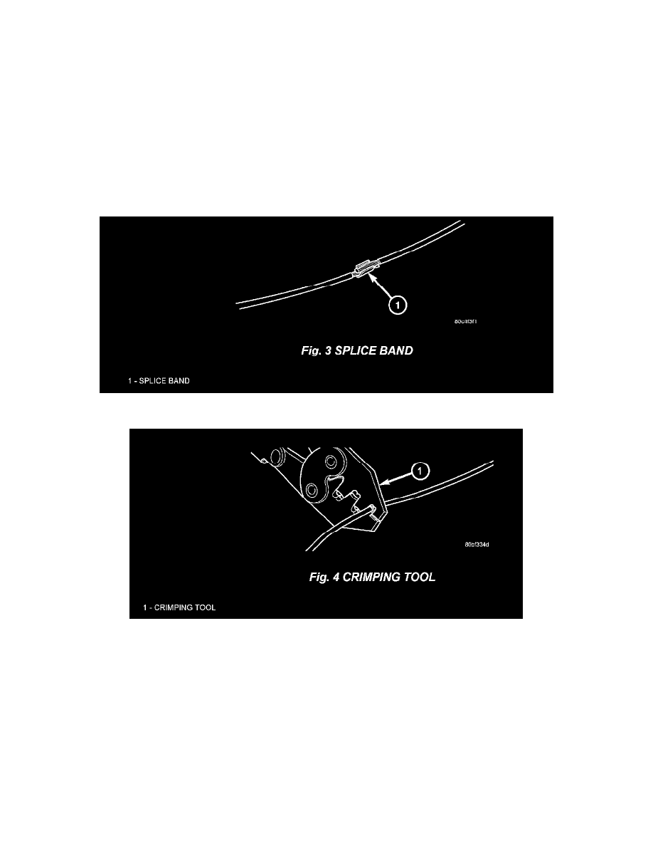
6.
Place the strands of wire overlapping each other inside of the splice band (Fig 3).
7.
Using crimping tool, Mopar p/n 05019912AA, crimp the splice band and wires together (Fig 4).