
PT Cruiser L4-2.4L Turbo (2009)
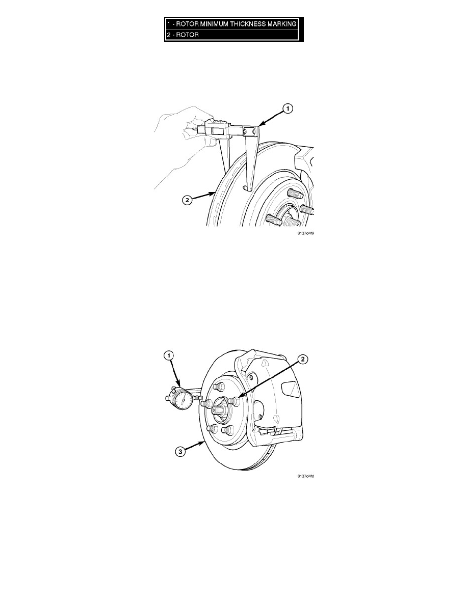
Minimum thickness specifications are cast on the rotor's unmachined surface (1). Limits can also be found in this component's specification table. See:
Specifications
ROTOR THICKNESS VARIATION
Thickness variation in a rotor's braking surface can result in pedal pulsation, chatter and surge. This can also be caused by excessive runout in the rotor
or the hub.
Rotor thickness variation measurements should be made in conjunction with measuring runout. Measure thickness of the brake rotor (2) at 12 equal
points around the rotor braking surface with a micrometer (1) at a radius approximately 25 mm (1 inch) from edge of rotor. If thickness measurements
vary beyond the specification listed in the specification table See: Specifications , the rotor should be refaced or replaced. See: Service and
Repair/Procedures.
ROTOR RUNOUT
On-vehicle rotor runout is the combination of the individual runout of the hub face and the runout of the brake rotor (hub runout can be measured
separately). To measure rotor runout on the vehicle:
1. Raise and support the vehicle. See: Maintenance/Vehicle Lifting/Service and Repair
2. Remove the tire and wheel assembly. See: Maintenance/Wheels and Tires/Service and Repair/Removal and Replacement/Tires and Wheels -
Removal
3. Install standard wheel mounting nuts, flat side to rotor, on all the wheel studs (2). Progressively tighten the nuts in a crisscross (star) pattern to 135
Nm (100 ft. lbs.).
4. Mount Dial Indicator (1), Special Tool C-3339A, with Wheel, Special Tool 25w, or equivalent, to the knuckle. Position the dial indicator wheel to
contact the rotor braking surface approximately 10 millimeters from the outer edge of the rotor (3).