
PT Cruiser L4-2.4L Turbo (2009)
Compressor Clutch: Testing and Inspection
A/C Clutch
A/C CLUTCH
The A/C clutch coil electrical circuit is controlled by the Powertrain Control Module (PCM) or Engine Control Module (ECM) (depending on engine
application) through the Totally Integrated Power Module (TIPM). The A/C clutch coil can be tested by either measuring coil resistance or current draw.
Begin testing of a suspected A/C clutch coil concern by performing the preliminary checks.
PRELIMINARY CHECKS
1. If the A/C compressor clutch will not engage, check for Diagnostic Trouble Codes (DTCs) in the Cabin Compartment Node (CCN), TIPM,
PCM/ECM and if equipped, the gateway module. If no DTCs are found go to 2. If any DTCs are found, repair as required.
2. If the A/C clutch still will not engage, verify the refrigerant charge level by conducting the A/C Performance test See: Testing and Inspection. If
the refrigerant charge level is OK, go to COIL RESISTANCE TEST and COIL CURRENT DRAW TEST. If the refrigerant charge level is
not OK, adjust the refrigerant charge as required.
COIL RESISTANCE TEST
1. Disconnect and isolate the negative battery cable.
2. Disconnect the wire harness connector from the A/C clutch coil connector.
3. Use an ohmmeter and Back Probe Tool 6801, measure the resistance of the A/C clutch coil at the coil connector terminals.
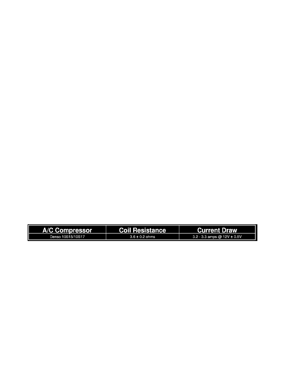
4. See the A/C Clutch Coil Specifications chart for the acceptable A/C clutch coil resistance. Specifications apply for a work area temperature of 21°
C (70° F).
a. If the A/C clutch coil reading is below specifications, the coil is shorted and must be replaced.
b. If the A/C clutch coil reading is above specifications, the coil is open and must be replaced.
COIL CURRENT DRAW TEST
1. Verify the battery state of charge See: Starting and Charging/Battery/Testing and Inspection/Battery.
2. Connect an ammeter (0 to 10 ampere scale selected) in series with the A/C clutch coil feed terminal using Back Probe Tool 6801. Connect a
voltmeter (0 to 20 volt scale selected) to measure voltage across the battery and the A/C clutch coil.
3. With the A/C-heater control in any A/C mode and the blower motor at low speed, start the engine and allow it to run at a normal idle speed.
4. The A/C clutch should engage immediately and the A/C clutch coil supply voltage should be within two volts of the battery voltage. If the A/C
clutch coil supply voltage is OK, go to 5. If the A/C clutch coil supply voltage is not within two volts of battery voltage, test the clutch coil feed
circuit for excessive voltage drop and repair as necessary.
5. See the A/C Clutch Coil Specifications chart for the acceptable A/C clutch coil current draw. Specifications apply for a work area temperature of
21° C (70° F). If voltage is more than 12.5 volts, add electrical loads by turning on electrical accessories until voltage reads below 12.5 volts.
A/C CLUTCH COIL SPECIFICATIONS