
PT Cruiser L4-2.4L Turbo (2009)
Lateral Stabilizer Rod: Description and Operation
Rear Suspension Watts Link - Description
DESCRIPTION
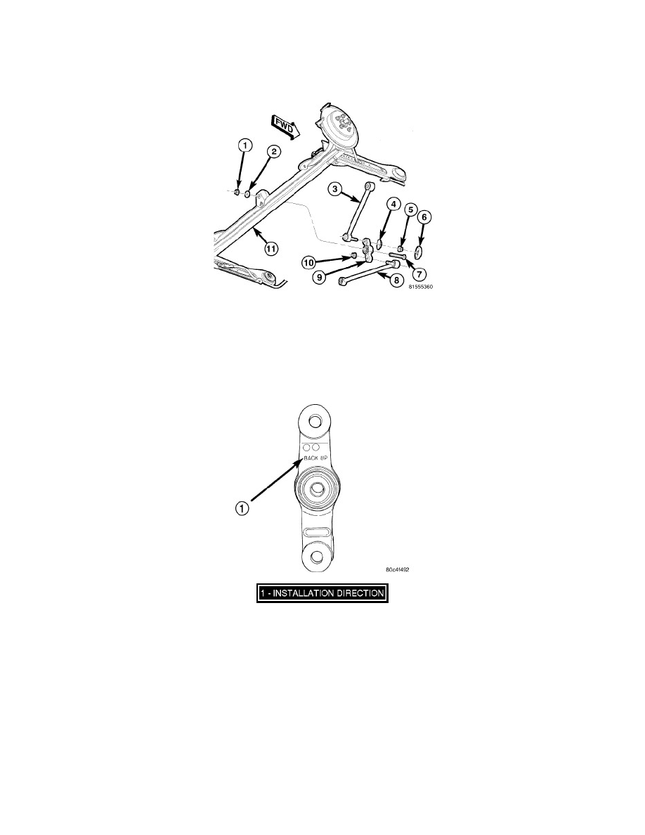
The watts link assembly consists of:
-
Bell Crank (9)
-
Lower Link (8)
-
Upper Link (3)
The bell crank mounts to the center of the rear axle (11) and the outboard ends of the two links mount to brackets on the body of the vehicle.
The cast iron bell crank has a non-serviceable sealed-for-life bearing mounted in the center of it through which it is fastened to the axle. It also has the
words "BACK UP" cast into one side of it indicating the installation direction when mounted to the axle. Although the pivot may look identical end to
end, it is not and must be installed with the words "BACK UP" toward the back of the vehicle facing upright in order to avoid premature bearing failure.
The upper and lower links both have ball joints on one end and bushings on the other. The ball joint ends connect to the bell crank and the bushing ends
connect to a bracket on the body. The upper link extends from the upper hole machined into the bell crank to a bracket on the right side of the vehicle.
The lower link extends from the lower hole machined into the bell crank to the bracket on the left side of the vehicle. Although the lower and upper links
look like steering tie rods, no attempt should be made to adjust them. They are fixed to a set length at the factory and require no maintenance. Neither the
ball joints, nor the bushings on the links are serviceable.