
PT Cruiser L4-2.4L Turbo VIN G (2004)
Electronic Brake Control Module: Description and Operation
CONTROLLER ANTILOCK BRAKE
The Controller Antilock Brake (CAB) is a microprocessor-based device which monitors the ABS system during normal braking and controls it when
the vehicle is in an ABS stop. The CAB uses a 24-way electrical connector on the vehicle wiring harness. The power source for the CAB is through
the ignition switch in the RUN or ON position. The CAB is on the PCI bus.
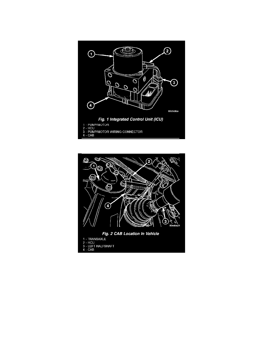
Fig. 1 Integrated Control Unit (ICU)
Fig. 2 CAB Location In Vehicle
The CAB is mounted to the HCU as part of the Integrated Control Unit (ICU). Attached to the bottom of the HCU, it can be viewed from below, just
above the transaxle and left halfshaft. For information on the ICU.
The primary functions of the controller antilock brake (CAB) are to:
-
monitor the antilock brake system for proper operation.
-
detect wheel locking or wheel slipping tendencies by monitoring the speed of all four wheels of the vehicle.
-
control fluid modulation to the wheel brakes while the system is in an ABS mode or the traction control system is activated.
-
store diagnostic information.
-
provide communication to the DRBIII(R) scan tool while in diagnostic mode.
The CAB constantly monitors the antilock brake system for proper operation. If the CAB detects a fault, it will send a message to the mechanical
instrument cluster (MIC) instructing it to turn on the amber ABS warning indicator lamp and disable the antilock braking system. The normal base