
PT Cruiser L4-2.4L Turbo VIN G (2004)
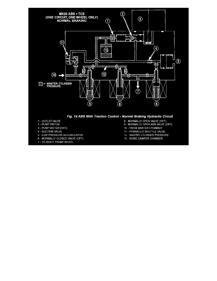
The hydraulic diagram shows a vehicle with traction control in the normal braking mode. The diagram shows no wheel spin or slip occurring relative
to the speed of the vehicle. The driver is applying the brake pedal; this builds pressure in the brake hydraulic system to engage the brakes and stop the
vehicle. The hydraulic shuttle valve closes with every brake pedal application so pressure is not created at the inlet to the pump/motor.
ABS BRAKING HYDRAULIC CIRCUIT, SOLENOID VALVE, AND SHUTTLE VALVE FUNCTION (ABS WITH TRACTION CONTROL)