
PT Cruiser L4-2.4L Turbo VIN G (2004)
If front camber is found not to meet alignment specifications, it can be adjusted using an available camber adjustment bolt package. Before installing a
camber adjustment bolt package on a vehicle found to be outside the specifications, inspect the suspension components for any signs of damage or
bending.
No adjustment can be made to the caster setting on this vehicle. If the vehicle's caster is not within alignment specifications, check for damaged
suspension components or body parts.
CAUTION: Do not attempt to adjust the vehicles wheel alignment by heating or bending any of the suspension components.
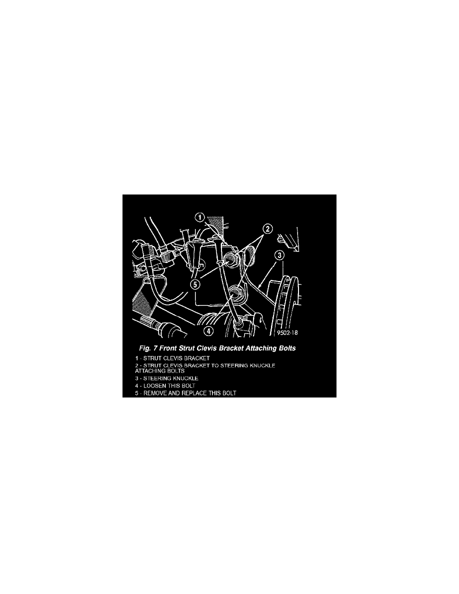
CAMBER ADJUSTMENT BOLT PACKAGE INSTALLATION
The camber adjustment bolt package contains new bolts and nuts for attaching the strut clevis bracket to the steering knuckle. The bolts contained in
the package are slightly undersize allowing for movement between the strut clevis bracket and the steering knuckle. The movement allowed by the
undersize bolts provide approximately two degrees of camber adjustment per side of the vehicle. To install and adjust the camber adjustment bolt
package, follow the procedure below.
1. Raise the vehicle until its tires are not supporting the weight of the vehicle.
CAUTION: The knuckle to strut assembly attaching bolt shanks are serrated and must not be turned during removal. Remove the nuts while
holding the bolts stationary.
2. Remove the original upper bolt attaching the strut clevis bracket to the knuckle.
3. Install a bolt from the adjustment package into the hole where the original bolt was removed. Install the bolt from the rear.
4. Install a nut provided in adjustment package on the replacement bolt. Tighten the nut until it's snug, but still allowing the knuckle to slide in the
clevis bracket.
5. Remove the original lower bolt.
6. Install a bolt from the adjustment package into the bottom hole of the strut clevis bracket. Install the bolt from the rear.
7. Install a nut provided in adjustment package on the replacement bolt. Tighten the nut until it's snug.
8. Reinstall the tire and wheel assembly. Tighten the wheel mounting nuts to a torque of 135 Nm (100 ft. lbs.).
9. Perform the above procedure to opposite strut as required.
10. Lower the vehicle and jounce the front and rear of the vehicle.
11. Adjust the front camber to the preferred setting by pushing or pulling on the top of the tire. When camber is set to specifications, tighten the upper
and lower strut clevis bracket bolts. Again jounce the front and rear of the vehicle, then verify the camber settings.
12. Torque front strut clevis bracket-to-steering knuckle attaching bolts to 53 Nm (40 ft. lbs.), plus an additional 1/4 turn after the torque is met.
13. Once camber is within specifications, adjust toe to meet the preferred specification setting.
FRONT TOE
1. Center the steering wheel and lock it in place using a steering wheel clamp.
CAUTION: Do not twist the inner tie rod-to-steering gear rubber boots while turning the inner tie rod during the front toe adjustment.