
PT Cruiser L4-2.4L Turbo VIN G (2004)
Electronic Brake Control Module: Service and Repair
CONTROLLER ANTILOCK BRAKE
REMOVAL
To remove the CAB, the ICU must be removed from the vehicle and disassembled.
1. Disconnect battery negative cable.
2. Raise vehicle.
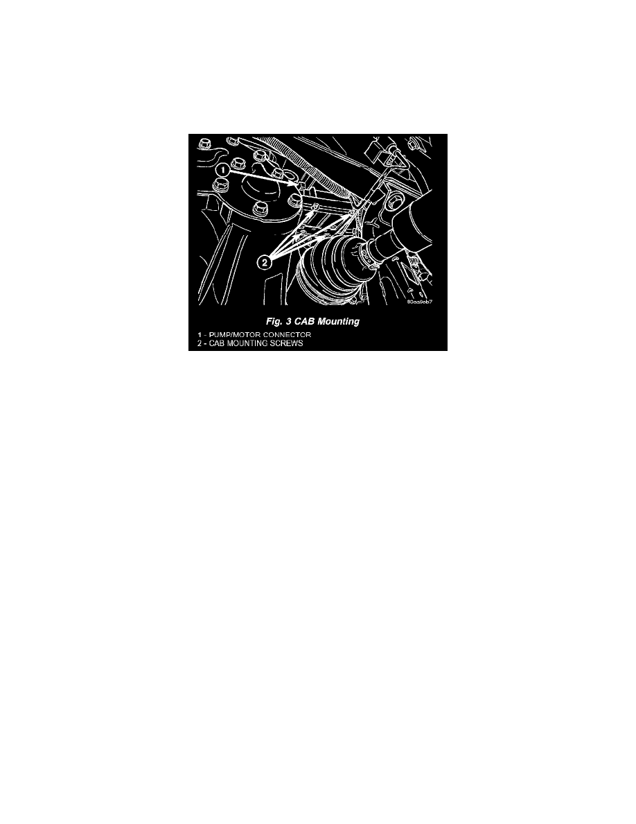
Fig. 3 CAB Mounting
3. Disconnect pump/motor connector from CAB.
4. Remove four screws securing CAB to HCU half of ICU. Remove CAB from HCU.
5. Pull outward on CAB connector lock and disconnect 24-way wiring connector. Remove CAB from vehicle.
INSTALLATION
To install the CAB, it must be attached to the HCU, forming the ICU.
1. Connect 24-way wiring connector to CAB and push in connector lock.
2. Align CAB with HCU half of ICU, then slide CAB up over HCU valves. Install four CAB mounting screws. Tighten mounting screws to 2 Nm (17
in. lbs.) torque.
3. Connect pump/motor connector.
4. Lower vehicle.
5. Connect battery negative cable.
6. Connect DRB III to vehicle to initialize system. Check and clear any faults