
Sebring L4-122 2.0L DOHC VIN Y MFI (1995)
9.
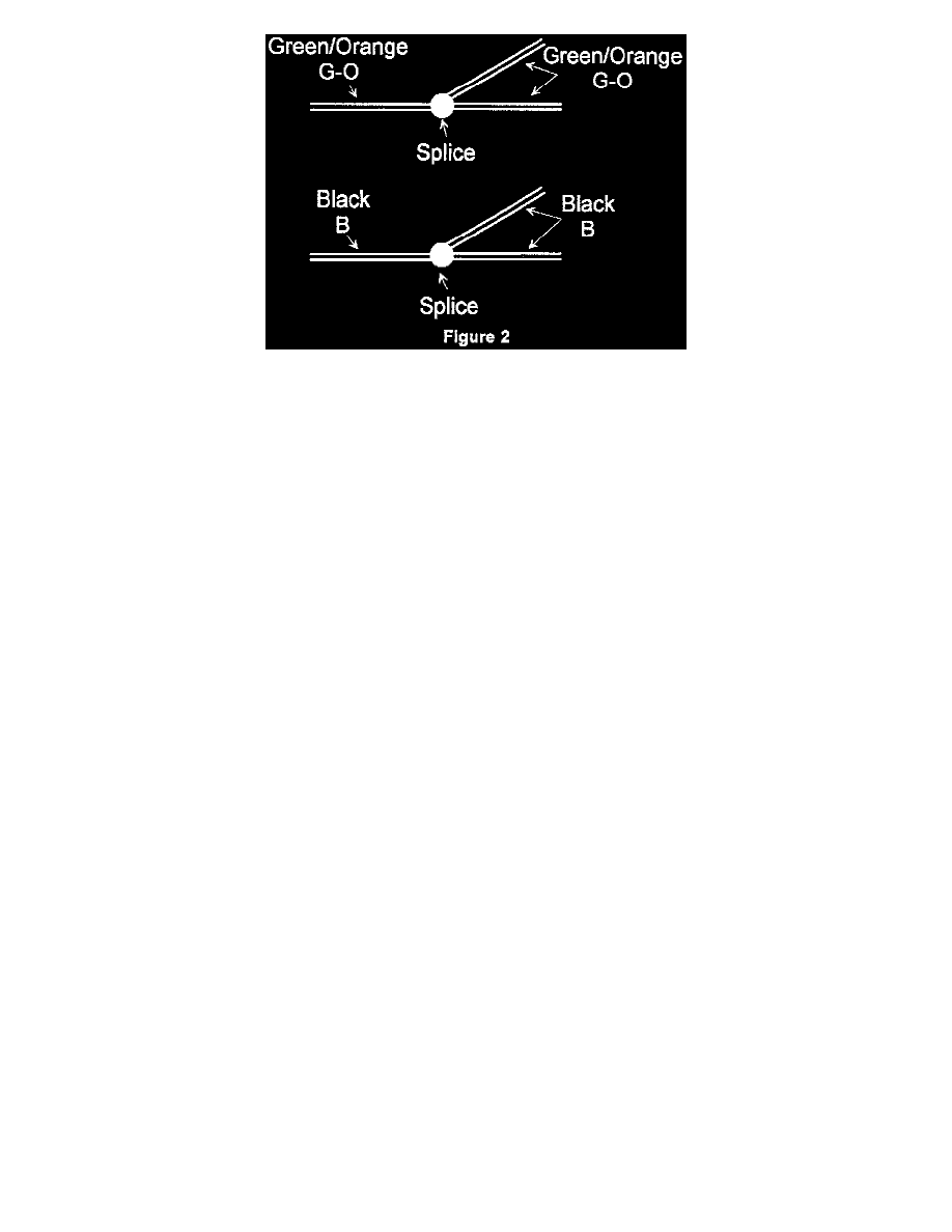
Locate the two splice joints (Figures 1 & 2). It will be necessary to remove the wiring from the protective convolute and any electrical tape to gain
access to the splices.
10.
Inspect both splice joints for any corrosion. If corrosion is found, remove the corroded portion and re-splice the same colored wires together. Use
the procedures outlined in step number 6 to properly repair the splices.
11.
If no corrosion is found at the splices, re-solder them using rosin core solder and seal each section with 3M Electrical Moisture Sealant Patch, P/N
06149, or Tape, P/N 06147.
12.
After the repair, place the wires back into the convolute. Wrap electrical tape around the convolute to prevent the wires from protruding.
13.
Install the ABS control unit shield (if equipped), fascia, splash shield and wheel. Lower the vehicle.
14.
Connect the negative battery cable and set the radio presets recorded in step number 1. Set the clock to the appropriate time.
15.
Verify proper operation of the vehicle before returning it to the customer.
POLICY: Reimbursable within the provisions of the warranty.
TIME ALLOWANCE:
Labor Operation No:
Inspect Wiring Harness Connector and Splices for Corrosion
08-94-CA-90
1.1 Hrs.
Remove Connector and Hard Wire
08-94-CA-91
0.3 Hrs.
Repair Splice Corrosion
08-94-CA-92
0.2 Hrs.
FAILURE CODE:
3T - Terminal(s) Corroded