
Sebring Convertible V6-2.5L SOHC 24 Valve (1996)
2. Remove hydraulic brake line from proportioning valve to be tested, then remove valve from master cylinder outlet port.
3. Install Pressure Test Fitting Tool No. 6805-1 or 6805-2, or equivalent, depending on the thread size, into rear brake tube.
4. Install proportioning valve into pressure test fitting.
5. Install Pressure Test Fitting Tool No. 6805-3 or 6805-4, or equivalent, depending on the thread size, into outlet port of proportioning valve.
6. Connect brake hydraulic line onto pressure test fitting on proportioning valve.
7. Install Pressure Gauge Set Tool No. C-4007-A, or equivalent, into test fitting and bleed air from pressure gauge hose.
8. Apply pressure to brake pedal until reading on proportioning valve inlet test fitting is appropriate, then check the pressure reading on the outlet test
fitting. If the pressure on the outlet test fitting is not within specifications.
9. Install proportioning valve and hand tighten until installed, then torque proportioning valve to 145 inch lbs.
10. Install brake tube onto proportioning valve and torque tube nut to 145 inch lbs.
11. Bleed brake line as outlined under Hydraulic Brake System/Service and Repair/Brake System Bleed.
WITH ANTI-LOCK BRAKE SYSTEM
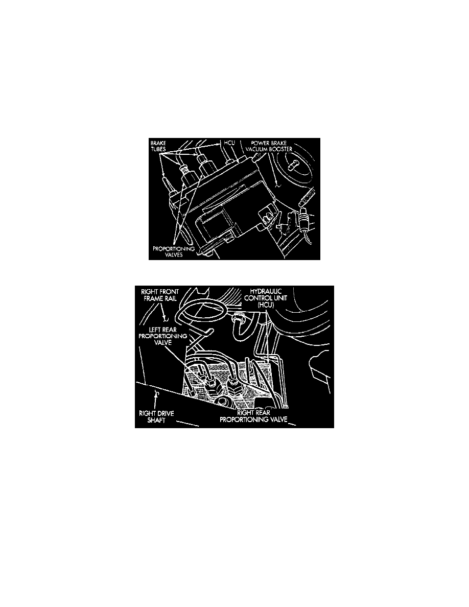
Fig 39 Type 3 Proportioning Valve Location
Fig 40 Type 3 Proportioning Valve Location
1. Road test vehicle to determine which rear wheel exhibits premature wheel skid. Determine which proportioning valve needs to be tested.
2. Remove hydraulic brake line from proportioning valve to be tested, then remove valve from master cylinder outlet port.
3. Install Pressure Test Fitting Tool No. 6805-1 or 6805-2, or equivalent, depending on the thread size, into outlet port of master cylinder.
4. Install proportioning valve into pressure test fitting in master cylinder outlet port.
5. Install Pressure Test Fitting Tool No. 6805-3 or 6805-4, or equivalent, depending on the thread size, into outlet port of proportioning valve.
6. Connect brake hydraulic line onto pressure test fitting on proportioning valve.
7. Install Pressure Gauge Set Tool No. C-4007-A, or equivalent, into test fitting and bleed air from pressure gauge hose.
8. Apply pressure to brake pedal until reading on proportioning valve inlet test fitting is appropriate, then check the pressure reading on the outlet test
fitting. If the pressure on the outlet test fitting is not within specifications, replace proportioning valve.
9. Install proportioning valve into master cylinder body until O-ring is seated, then torque proportioning valve to 30 ft. lbs.
10. Install brake tube onto proportioning valve and torque tube nut to 145 inch lbs.
11. Bleed brake line as outlined under Hydraulic Brake System/Service and Repair/Brake System Bleed.