
Sebring Convertible V6-2.5L SOHC 24 Valve (1996)
Control Arm: Service and Repair
Front
Upper
1. Raise and support vehicle, then remove the front wheel and tire assembly.
2. Remove vehicle speed sensor cable routing bracket.
3. Remove cotter pin and castle nut from upper ball joint stud to steering knuckle attachment.
4. Remove upper ball joint stud from steering knuckle using puller tool No. C-3894-A, or equivalent, then position the steering outward toward rear
of wheelwell.
5. Remove pinch bolt attaching shock clevis to shock.
6. Remove through bolt attaching shock to lower control arm.
7. Remove clevis from shock by carefully tapping clevis with soft brass drift off shock fluid reservoir.
8. Remove four bolts attaching upper control arm/shock absorber mounting bracket to shock tower.
9. Remove shock absorber and upper control arm mounting bracket as an assembly.
10. Reverse procedure to install.
Lower
1. Raise and support vehicle, then remove the front wheel and tire assembly.
2. On models equipped with 15 inch wheels, remove lower ball joint heat shield.
3. On all models, remove disc brake caliper and support aside, then the brake disc.
4. Disconnect ball joint from steering knuckle, then turn steering knuckle so front of knuckle is facing as far outboard as possible.
5. Separate steering knuckle from lower ball joint by lightly tapping with a rubber mallet.
6. Remove shock absorber clevis from lower control.
7. Using an Allen wrench to prevent stabilizer bar link from rotating, remove nut attaching stabilizer bar link assembly to lower control arm.
8. Remove attaching bolts of stabilizer bar bushing to front suspension crossmember and body of vehicle.
9. Lower one side of stabilizer bar away from lower control arm.
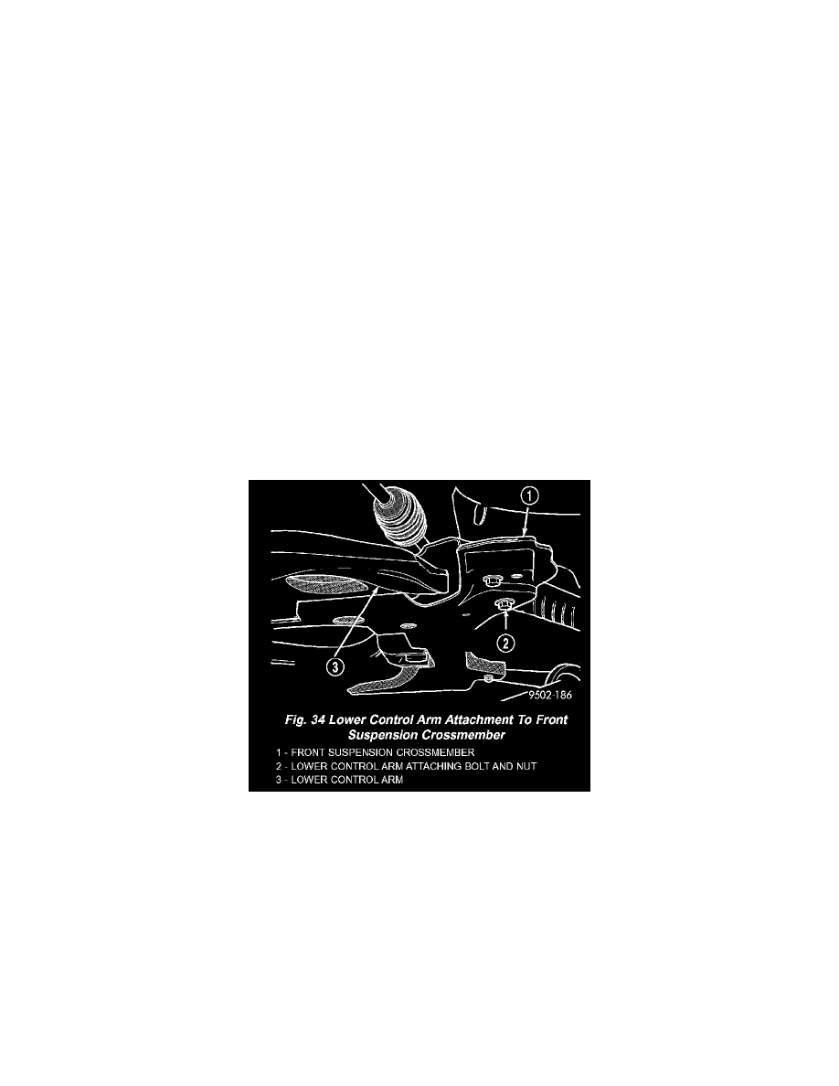
10. Remove nut and bolt attaching rear isolator bushing of lower control arm then the nut and bolt attaching front isolator bushing of lower control
arm.
11. Remove front isolator bushing of lower control arm to front suspension crossmember.
12. To remove lower control arm, proceed as follows:
a. Remove front of lower control arm from front suspension crossmember first.
b. Remove rear of lower control arm from between the top and bottom half of front suspension crossmember, keeping lower control arm as level
as possible.
13. Reverse procedure to install.