
Sebring Convertible V6-2.5L VIN H (1997)
Powertrain Control Module: Description and Operation
Electrical Tests At Powertrain Control Module
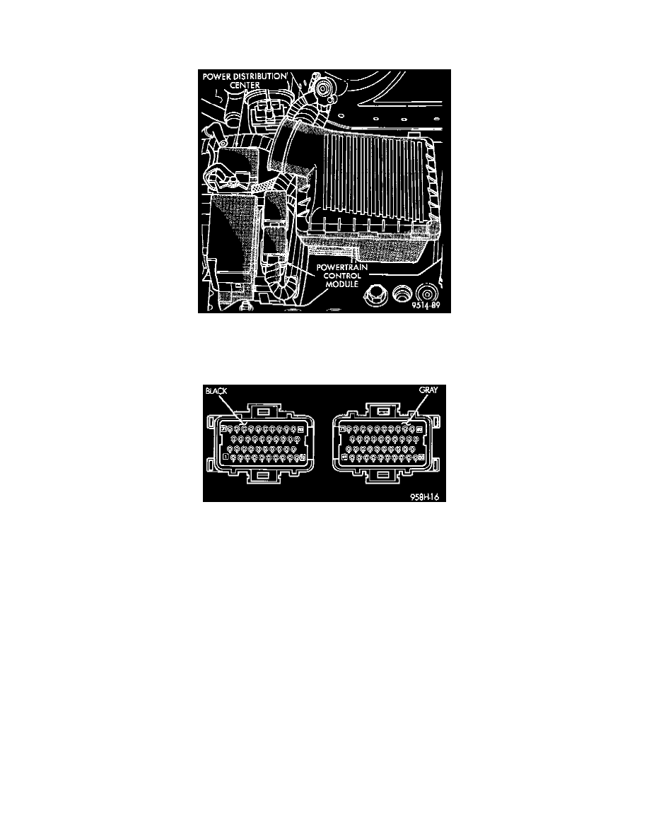
Powertrain Control Module Location
1. Unplug 2 40-way connectors from the Power-train Control Module (PCM).
2. Remove both steering wheel speed control switches and disconnect the wire connectors.
PCM 40-Way Connectors
a. Using an ohmmeter, check for continuity between pin 41 of the PCM connector and pin 1 of each speed control switch connector.
b. If no continuity, repair as necessary.
c. Using an ohmmeter, check for continuity between pin 41 of the PCM connector and ground.
d. If continuity, repair the short circuit.
e. If no continuity, perform the Switch Test.
3. Place ignition switch in the ON position for the following tests.
a. Connect wire connectors to both switches.
b. Using a voltmeter, connect the ground lead to ground.
c. Touch the positive lead of the voltmeter to pin 5 on the PCM. Depress the ON switch, the voltmeter should read battery voltage. Depress OFF
switch, the voltmeter should read 0 Volts. If no voltage, repair wire between pin 80 and pin 2 of the servo. If OK, go to step 4.
d. Reconnect the BLACK connector (with pins 1-40) to PCM.
e. Touch the positive lead of the voltmeter to the harness connector pin 80. Depress OFF switch, the voltmeter should read 0 Volts. Depress ON
switch, the voltmeter should read battery voltage. If no voltage, go to step 5. Repair the wire between pin 78 and 1 of the speed control servo.
If OK, go to step 5.
4. Disconnect the 4 way connector at the servo. Depress the ON switch. The voltmeter should read battery volts at pin 3. If no voltage go to step 7. If
voltage is OK, repair wire between pin 80 and pin 2 of the servo.
5. Reconnect the 4 way connector to servo.
6. Touch the positive lead of the voltmeter to the harness connector pin 80. Depress OFF switch, the voltmeter should read 0 Volts. Depress ON
switch, the voltmeter should read battery voltage. If no voltage, go to step 5. Repair the wire between pin 80 and pin 1 of the speed control servo.
If OK, go to step 5.
7. Turn key off.
8. Using an ohmmeter, connect one lead to ground and touch the other lead to pin 62. With the brake pedal released, the meter should show
continuity If no continuity, perform the following test: