
Sebring Convertible V6-2.7L (2009)
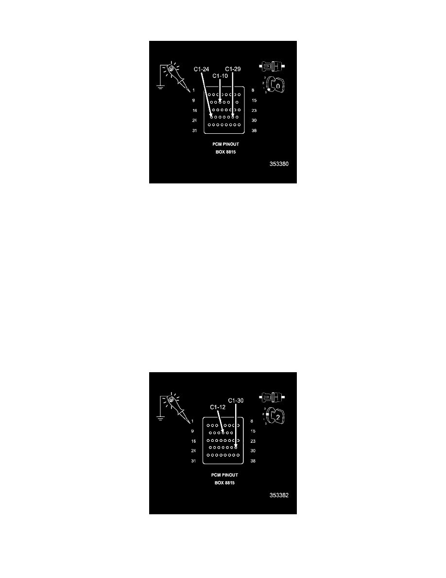
3. CHECKING THE PCM POWER SUPPLY CIRCUITS
CAUTION: Do not probe the PCM harness connectors. Probing the PCM harness connectors will damage the PCM terminals resulting in
poor terminal to pin connection. Install PCM Pinout Box 8815 to perform diagnosis.
1. Using a 12-volt test light connected to ground, check the PCM power supply circuits.
2. Wiggle test each circuit during the test to check for an intermittent open in the circuit.
NOTE: The test light should be illuminated and bright. Compare the brightness to that of a direct connection to the battery.
Is the test light illuminated and bright?
Yes
-
Go To 4
No
-
Repair the PCM power supply circuit(s) for an open circuit or high resistance.
-
Perform the PCM VERIFICATION TEST. See: Computers and Control Systems/Testing and Inspection/Diagnostic Trouble Code Tests and
Associated Procedures/Verification Tests/PCM Verification Test.
4. CHECKING THE PCM SWITCHED POWER SUPPLY CIRCUITS
1. Turn the ignition on.
2. Using a 12-volt test light connected to ground, check the PCM switched power supply circuits.
3. Turn the ignition off.
4. Using a 12-volt test light connected to ground, check the PCM switched power supply circuits.