
Sebring LX Coupe V6-3.0L VIN H (2002)
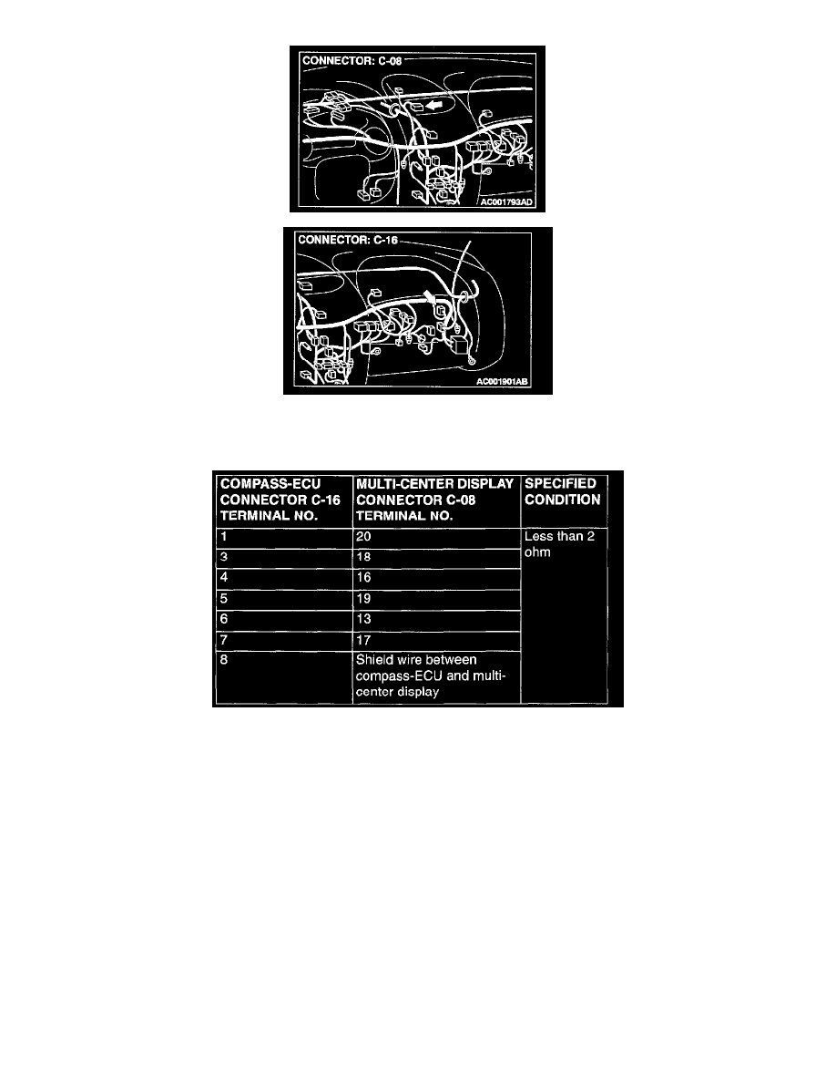
STEP 4. Check the compass-ECU connector C-16 and multi-center display connector C-08 by backprobing.
1. Do not disconnect the compass-ECU connector C-16 and multi-center display connector C-08, measure at the harness side.
2. Measure the resistance between compass-ECU connector C-16 and multi-center display connector C-08 by backprobing.
Q: Is the resistance value less than 2 ohm?
YES: Replace the compass-ECU.
NO: Repair or replace it. Refer to Harness Connector Inspection.
Inspection Procedure 3
The Compass is not Displayed Correctly.
STEP 1. Check the vehicle location
Q: Are there any constructions, such as high-voltage wires or a steel bridge, which might affect the compass sensor?
YES: After moving to a location where the magnetic field is stable, check the faulty condition again.
NO: Go to Step 2.
STEP 2. Correct magnetization
Q: Was magnetization corrected?