
Sebring LX Coupe V6-3.0L VIN H (2002)
TECHNICAL DESCRIPTION (COMMENT)
It is suspected that the power supply circuit to the front-ECU is defective, or the wiring harness between the SWS monitor kit and the front-ECU or their
connector(s) is damaged. If the battery power supply circuit to the ECU (terminal No.7 of the front ECU) is damaged, also check the power supply
circuit from the ignition switch (IG2) (terminal No.30 of the front-ECU), and repair if necessary.
TROUBLESHOOTING HINTS
-
The front-ECU may be defective
-
The ETACS-ECU may be defective
-
The wiring harness or connectors may have loose, corroded, or damaged terminals, or terminals pushed back in the connector
DIAGNOSIS
Required Special Tools:
-
MB991223: Harness Set
-
MB991502: Scan Tool (MUT-II)
STEP 1. Verify the ignition switch position.
Q: Does DTC 13 set with the ignition switch at "ON" position?
YES: Go to Step 5.
NO: Go to Step2.
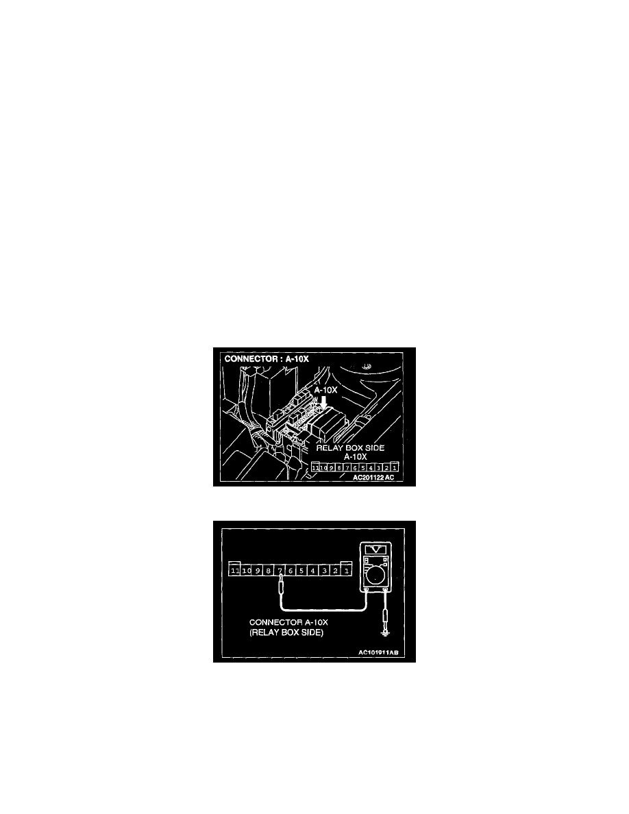
STEP 2. Check the battery power supply circuit to the front-ECU. Test at front-ECU connector A-10X.
1. Disconnect the front-ECU connector A-10X and measure the voltage available at the relay box side of the connector.
2. Measure the voltage between terminal 7 and ground.
-
The voltage should equal approximately 12 volts (battery positive voltage).
Q: Is the measured voltage approximately 12 volts (battery positive voltage)?
YES : Replace the front-ECU. Confirm the DTC 13 is not displayed.
NO : Go to Step 3.