
Sebring LX Coupe V6-3.0L VIN H (2002)
Q: Does the hazard warning light illuminate?
YES : Go to Step 2 <when using scan tool MB991502> or 3 <when using a voltmeter>.
NO : Check the ETACS-ECU battery circuit. Refer to Inspection Procedure P-1. See: Diagnosis By Symptom/Symptom Procedures/Inspection
Procedure P-1
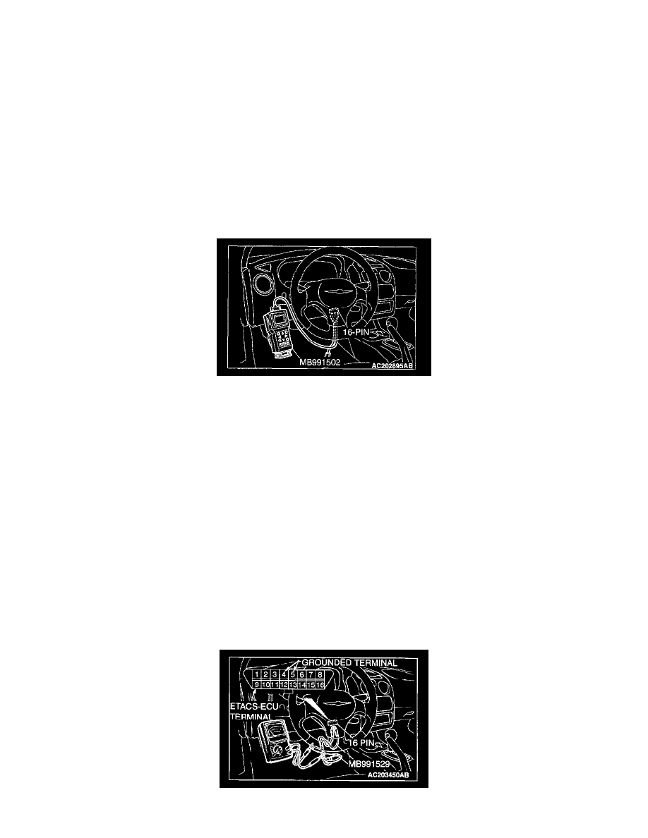
STEP 2. Check the input signal (by using scan tool MB991502).
Check the input signals from the following switches:
-
Ignition switch (IG1)
-
Key reminder switch
-
Driver's door switch
CAUTION: To prevent damage to scan tool MB991502, always turn the ignition switch to the "LOCK" (OFF) position before connecting or
disconnecting scan tool MB991502.
1. Connect scan tool MB991502 to the data link connector.
2. Check that the tone alarm of scan tool MB991502 sounds when the input signal enters.
Q: Does the tone alarm of scan tool MB991502 sound when the input signal enters?
YES : Replace the ETACS-ECU. The ignition key reminder tone alarm function should work normally.
NO:
-
Scan tool MB991502 does not sound when the ignition switch is turned from "ACC" to "ON": Refer to Inspection Procedure O-2 "The
ignition switch (IG1) signal is not sent to the ETACS-ECU." See: Diagnosis By Symptom/Symptom Procedures/Inspection Procedure O-2
-
Scan tool MB991502 does not sound when the ignition key is inserted and then removed: Refer to Inspection Procedure O-3 "The key
reminder switch signal is not sent to the ETACS-ECU." See: Diagnosis By Symptom/Symptom Procedures/Inspection Procedure O-3
-
Scan tool MB991502 does not sound when the driver's door is opened: Refer to Inspection Procedure O-8 "The driver's or passenger's door
switch signal is not sent to the ETACS-ECU." See: Diagnosis By Symptom/Symptom Procedures/Inspection Procedure O-8
STEP 3. Check the input signal (by using a voltmeter).
Check the input signals from the following switches:
-
Ignition switch (IG1)
-
Key reminder switch
-
Driver's door switch
1. Use special tool MB991529 to connect a voltmeter between ground terminal 4 or 5 and ETACS-ECU terminal 9 of the data link connector.