
Sebring LXI Convertible V6-2.7L VIN R (2002)
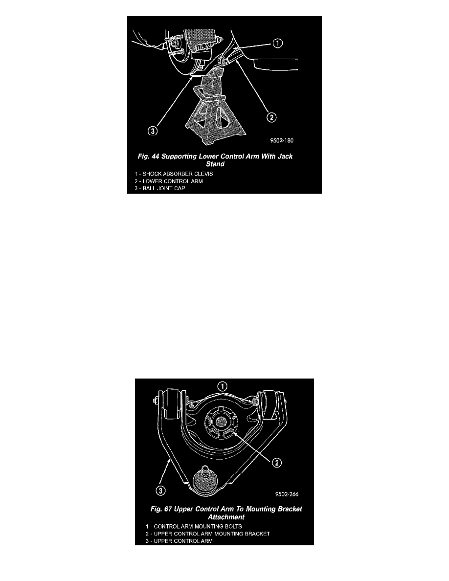
CAUTION: When supporting lower control arm with jack stand, do not position jack stand under the ball joint cap on the lower control arm.
Position in area of lower control arm shown in.
10. Lower vehicle to the ground with a jack stand positioned under the lower control arm. Continue to lower vehicle so the total weight of the vehicle
is supported by the jack stand and lower control arm.
CAUTION: When tightening the thru-bolt, do not turn the bolt in the clevis. The serrations on the bolt and the hole in the clevis will be damaged.
11. With the vehicle's suspension at curb height, tighten the clevis to lower control arm bushing thru-bolt nut to a torque of 88 Nm (65 ft. lbs.).
12. Tighten front lower control arm nut and bolt to a torque of 182 Nm (135 ft. lbs.).
13. Install wheel and tire assembly.
14. Tighten the wheel mounting stud nuts in proper sequence until all nuts are torqued to half specification. Then repeat the tightening sequence to the
full specified torque of 135 Nm (100 ft. lbs.).
15. Remove jack stand from under lower control arm and lower vehicle to the ground.
16. Check the vehicles alignment specifications and set front Toe to preferred specifications.
Upper Control Arm
REMOVAL - UPPER CONTROL ARM
1. Remove the front shock assembly from the vehicle.
2. Disassemble the shock assembly until the upper mounting bracket is removed from the coil spring.
3. Remove the 2 bolts attaching the upper control arm to the bushings in the upper mounting bracket.