
Sebring LXI Sedan V6-2.7L VIN R (2002)
Seat Heater: Description and Operation
HEATED SEAT SYSTEM
Individually controlled electrically heated front seats are available factory-installed optional equipment on this model. Vehicles with this option
can be visually identified by the heated seat switch mounted in the center console. The heated seat system allows the front seat driver to select
from six different levels of supplemental electrical seat heating, or no seat heating to suit their individual comfort requirements. The heated seat
system for this vehicle includes the following major components, which are explained in detail:
-
Heated seat switch - One heated seat switch is used per vehicle. The switch is mounted in the center console, behind the gear selector and has
two rotary knobs, one for the driver and one for the passenger front seats. There are three Light Emitting Diodes (LED's) in the heated seat
switch. The first LED illuminates the heated seat symbol on the switch anytime the ignition switch is in the ON position. The remaining LED's
illuminate the numbers on the switch, indicating that the heated seat system is on.
-
Heated seat module - One heated seat module is used per vehicle, this module contains the solid state electronic control and diagnostic logic
circuitry for the heated seat system. One heated seat module is used per vehicle and is mounted under the drivers front seat cushion. Refer to
the Electronic Control Modules section for heated seat module information.
-
Heated seat elements - Three heated seat elements are used per vehicle, two in the seat cushion and one in the seat back. These three
elements,which are integral to the individual front seat cushion and front seat back trim covers are connected in series with the heated seat
module.
-
Heated seat sensor - One heated seat sensor is used per vehicle, one for the single heated seat and is integrated into the seat cushion heating
element. The temperature sensor is a negative temperature coefficient thermistor.
Following are general descriptions of the major components in the heated seat system. See the owner's manual in the vehicle glove box for more
information on the features, use and operation of the heated seat system. Refer to Wiring Diagrams in the index for the location of complete heated
seat system wiring diagrams.
The heated seat module receives fused battery current through Junction Block (JB) only when the ignition switch is in the run position. The heated
seat switches receive battery current through a fused ignition switch output (run) circuit only when the ignition switch is in the Run position. The
heated seat module shares a common ground circuit with each of the heated seat elements. The heated seat elements will only operate when the
surface temperature of the seat cushion cover at the heated seat sensors is below the designed temperature set points of the system.
The heated seat module will automatically turn OFF the heated seat elements if it detects a short in the heated seat element circuit or a heated seat
sensor value that is out of range. The heated seat system will remain ON anytime the ignition switch is turned to the ON position and the heated
seat switch is at any of the # 1 through # 6 positions.
The heated seat module monitors inputs from the heated seat sensors and the heated seat switches. In response to these inputs the heated seat
module uses its internal programming to control outputs to the heated seat elements in both front seats and to control the heated seat LED indicator
lamps located in both of the heated seat switches.
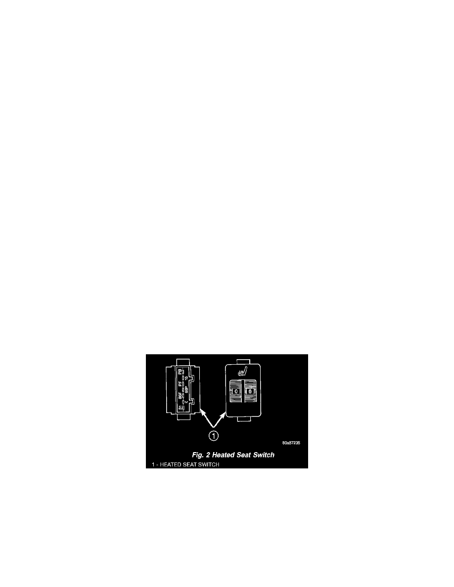
Heated Seat Switch
HEATED SEAT SWITCH
The heated seat switch used on vehicles with this option is mounted in the center console. The switch is snapped into a mounting hole in the center
console. The heated seat switch incorporates two rotary knobs, one for the driver and one for the front seat passenger. These knobs have numerals
1-6 to indicate the desired rate of supplemental seat heating. The instrument panel wire harness connectors for the heated seat switch is keyed to
match the connector receptacle on the switch so that the heated seat switch can only be connected in the proper orientation.
The heated seat switch cannot be repaired. If the indicator or back lighting lamps are faulty or damaged, the individual heated seat switch unit must
be replaced.