
Sebring LXI Sedan V6-27L VIN R (2002) | Seat Heater Component Info | Diagrams
The heated seat switches receive battery current through a fused ignition switch output (run) circuit when the ignition switch is in the ON position.
The two six-position rotating-type switches provide a hard-wired voltage signal to the heated seat module to power the heated seat element of the
selected seat and maintain the requested temperature setting.
There are three Light Emitting Diodes (LED's) in the heated seat switch. The first LED illuminates the heated seat symbol on the switch anytime
the ignition switch is in the ON position. The remaining LED's illuminate the numbers on the switch, indicating that the system is on.
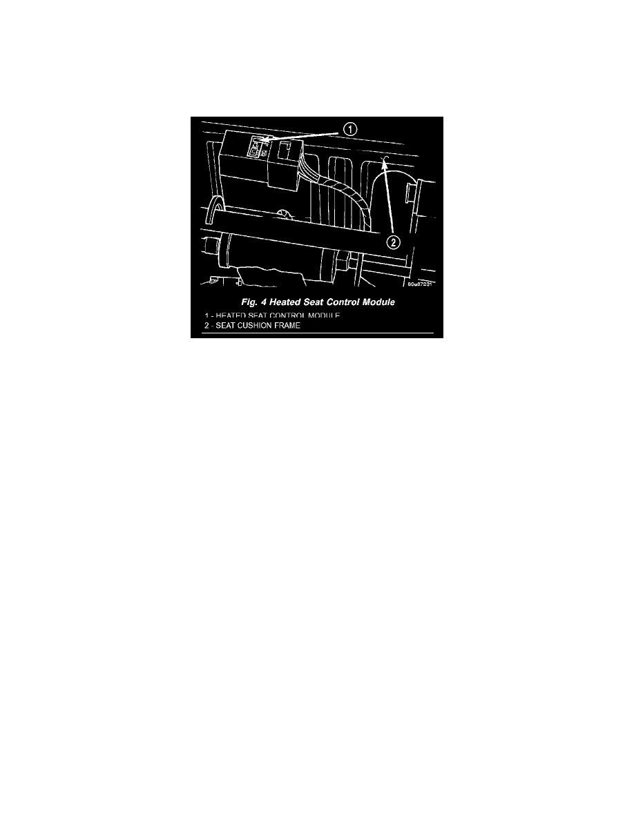
Fig.4 Heated Seat Control Module
HEATED SEAT MODULE
Two heated seat modules are used on this vehicle, one for each front seat. The heated seat modules are located under each front seat. The heated
seat module has a single connector receptacle that allows the module to be connected to all of the required inputs and outputs through the body
wire harness.
The heated seat module is an electronic microprocessor controlled device designed and programmed to use inputs from the ignition switch, the two
heated seat switches and the two heated seat sensors to operate and control the heated seat elements in both front seats.
The heated seat module cannot be repaired. If the heated seat module is damaged or faulty, the entire module must be replaced.
The heated seat module operates on fused battery current received from the ignition switch. The module is grounded at all times through the body
harness. Inputs to the module include a resistor multiplexed heated seat switch request circuit for each of the two heated seat switches and the
heated seat sensor inputs from the seat cushions of each front seat. In response to those inputs the heated seat module controls battery current feeds
to the heated seat elements and sensors.
When a heated seat switch (Driver or Passenger) request signal is received by the heated seat module, the module energizes the selected heated
seat sensor circuit and the sensor provides the module with an input indicating the surface temperature of the selected seat cushion.
The Low heat set point is about 38° C (100.4° F), and the High heat set point is about 42° C (107.6° F). If the seat cushion surface temperature
input is below the temperature set point for the selected temperature setting, the heated seat module energizes an N-channel Field Effect Transistor
(N-FET) within the module which energizes the heated seat elements in the selected seat cushion and back. When the sensor input to the module
indicates the correct temperature set point has been achieved, the module de-energizes the N-FET which de-energizes the heated seat elements.
The heated seat module will continue to cycle the N-FET as needed to maintain the selected temperature set point.
HEATED SEAT ELEMENT
Vehicles equipped with the optional heated seat system have two sets of electrically operated heating element grids located in each outboard
seating position of the front seat, one set for the seat cushion and the other set for the seat back. Each of the heated seat element grids consists of a
single length of resistor wire that is routed in a zigzag pattern and captured between the leather trim cover and the foam rubber backing on the
underside of its respective seat cushion trim cover and seat back trim cover assembly. Short pigtail wires with connectors are soldered to each end
of each resistor wire element grid, which connect all of the element grids for each seating position to each other in series with the heated seat
module through the seat wire harness.
One temperature sensor is used for each outboard seating position of the front seat, and it is located in the center insert area of the seat cushion
cover. The heated seat sensors and their pigtail wires are also captured between the leather trim cover and the foam rubber backing on the
underside of their respective seat cushion trim cover assemblies. The heated seat sensors are Negative Thermal Coefficient (NTC) thermistors.
The sensors for both front seats receive a voltage feed from a single output of the heated seat module, but the module receives individual sensor