
Sebring LXI Sedan V6-2.7L VIN R (2002)
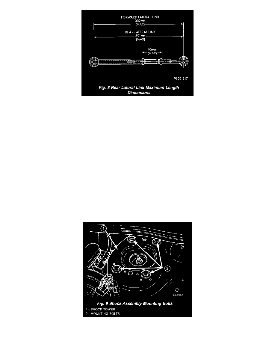
CAUTION: When setting rear camber and toe on the vehicle, the maximum lengths of the adjustable lateral link at the locations shown must not
be exceeded. If these maximum lengths are exceeded, inadequate retention of adjustment link to the inner and outer link may result.
2. Rough-in the rear camber setting as close as possible to the preferred specification by mainly adjusting the rear lateral link adjusting screw. Some
adjustment of the forward lateral link adjusting screw will also be required to get the rear camber setting to the preferred specification.
3. Adjust the forward lateral link adjusting screw to set rear toe to the preferred specification.
NOTE: Adjusting toe will cause a slight change in the camber setting. If during the setting of toe, camber is no longer at the preferred
specification, continue to adjust camber and toe until both are at their preferred specifications.
4. While holding adjustment screws from turning, use a crow foot and torque wrench, and tighten all lateral link adjusting screw jam nuts to a torque
of 92 Nm (68 ft. lbs.). This will securely hold the adjusting screws from turning.
5. Proceed to FRONT CASTER AND CAMBER, or FRONT TOE if front caster and camber are within specifications.
FRONT CAMBER AND CASTER
Camber and caster settings on this vehicle are determined at the time the vehicle is designed, by the location of the vehicle's suspension components.
This is referred to as NET BUILD. The result is no required adjustment of camber and caster after the vehicle is built or when servicing the
suspension components. Thus, when performing a wheel alignment, caster and camber are not normally considered adjustable angles. Camber and
caster should be checked to ensure they meet vehicle specifications.
If front camber is found not to meet alignment specifications, it can be adjusted using a procedure listed here. Before performing the camber
adjustment procedure, inspect the suspension components for any signs of damage or bending.
CAMBER ADJUSTMENT PROCEDURE
1. Open the hood and mark the position of all four shock assembly mounting bolts on the shock tower on the side of the vehicle requiring front
camber adjustment.
2. Raise the vehicle by the frame until the tires and front suspension are not supporting the weight of the vehicle.
3. Loosen the shock assembly mounting bolts on the side marked in step 1. Loosen the bolts enough to allow adequate space for removal of the