
Sebring Sedan L4-2.4L VIN J (2004)
Hydraulic Control Assembly - Antilock Brakes: Description and Operation
HCU (Hydraulic Control Unit)
HYDRAULIC CONTROL UNIT (HCU)
DESCRIPTION
HYDRAULIC CONTROL UNIT
The Hydraulic Control Unit (HCU) contains the valve block assembly, and pump/motor assembly.
Valve Block Assembly: The valve block assembly contains valves with four inlet valves and four outlet valves. The inlet valves are spring-loaded in
the open position and the outlet valves are spring loaded in the closed position. During an antilock stop, these valves are cycled to maintain the proper
slip ratio for each wheel. The CAB monitors wheel speeds. If the CAB detects a wheel deceleration that is disproportionate to the other wheels, it will
close the inlet valve to that wheel. This prevents any increase in fluid pressure. If the wheel continues to decelerate disproportionately, the CAB opens
the outlet valve for that wheel to release fluid pressure from that channel. The released fluid is routed to the accumulators. When the wheel speed is no
longer disproportionate to the other wheels, the inlet valve will return to its normally open position and the outlet valve will return to the normally
closed position. With a traction control system, there are two additional valves that isolate the master cylinder and rear wheels. During a traction
control situation the brakes are applied at a slipping drive wheel to reduce wheel slippage.
Pump Motor Assembly: The pump motor assembly provides the extra amount of fluid needed during antilock braking. The pump is supplied fluid
that is released to the accumulators when the outlet valve is opened during an antilock stop. The pump is also used to drain the accumulator circuits
after the antilock stop is complete. The pump is operated by an integral electric motor. This motor is controlled by the CAB. The CAB may turn on the
pump motor when an antilock stop is required. The pump continues to run during the antilock stop and is turned off after the stop is complete. Under
some conditions, the pump/motor will run to drain the accumulators during the next drive off. The CAB monitors the pump/motor operation internally.
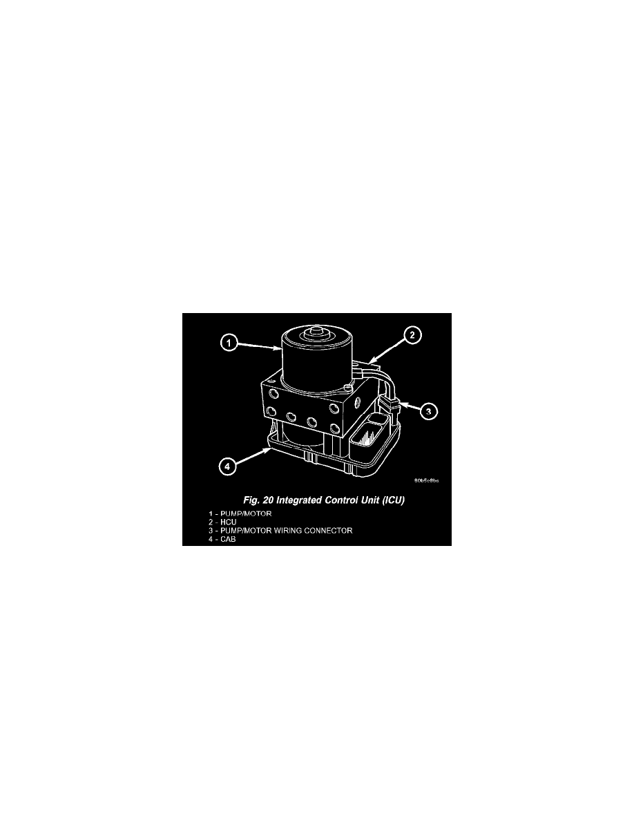
The Hydraulic Control Unit (HCU) is mounted to the CAB as part of the ICU (Fig. 20). The HCU controls the flow of brake fluid to the brakes using
a series of valves and accumulators. A pump/motor is mounted on the HCU to supply build pressure to the brakes during an ABS stop.
OPERATION - HYDRAULIC CIRCUITS AND VALVES
The hydraulic fluid control valves within the HCU control the flow of pressurized brake fluid to the wheel brakes during the different modes of ABS
braking. The following paragraphs explain how this works. For purposes of explanation only, it is assumed that only the right front wheel is
experiencing antilock braking; the following diagrams show only the right front wheel in an antilock braking operation.
NORMAL BRAKING HYDRAULIC CIRCUIT AND SOLENOID VALVE FUNCTION (ABS WITHOUT TRACTION CONTROL)