
Sebring Sedan L4-2.4L VIN J (2004)
Rear brake shoe lining should show contact across the entire width of the lining and also from the heel to the toe of the lining. Replace the shoes if
noted otherwise.
Brake shoes with lack of contact at the toe or heel of the brake shoe lining may be improperly ground.
Clean and inspect the brake support plate and shoe adjuster screw. Apply a thin coat of Mopers Multi-Purpose Grease or equivalent to the threads of
the self-adjuster. Replace the adjuster screw if it is corroded.
NOTE: Adjuster screws are different side-to-side. Left side adjuster screws have left-hand threads and right side adjuster screws have right-handed
threads.
If the old brake shoe return or hold down springs have overheated or are damaged, replace them. Overheating indications are paint discoloration or
distorted end coils.
INSTALLATION
NOTE: Perform Step 1 through Step 11 on each side of vehicle to complete shoe set installation, then proceed to Step 12.
1. Lubricate six shoe contact areas on support plate and anchor using Mopers Brake Lubricant or equivalent.
2. Before installing shoes on vehicle, perform the following on the bench:
a) Place one leading and one trailing shoe on bench (trailing shoe has parking brake lever attached to it).
b) Install adjuster and upper spring (Fig. 19).
c) Slide lever pawl under adjuster and onto pivot on leading shoe.
d) Install adjuster spring between leading shoe and lever pawl (Fig. 19).
3. Install pre-assembled brake shoe assembly on brake support plate (Fig. 18).
4. Install lower return spring (Fig. 18).
5. Install both shoe hold-down pins from rear, through support plate and shoes. Compress and install shoe hold-down springs on pins (Fig. 18).
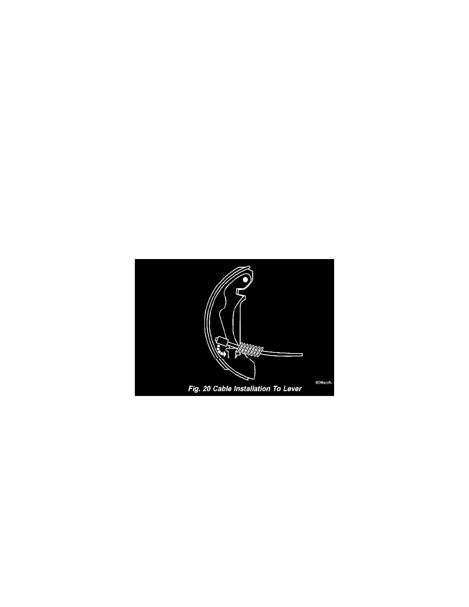
6. Compress parking brake cable return spring, then install cable on parking brake lever (Fig. 20). Release spring guiding it beneath retaining tab on
lever.
7. Insert cable into cable guide attached to anchor retaining plate.
8. Slide hub and bearing onto spindle (Fig. 16). Install retaining nut and tighten to 250 Nm (185 ft. lbs.) torque.
9. Install hub and bearing dust cap (Fig. 16).
10. Adjust brake shoes to drum diameter using brake shoe gauge.
11. Install brake drum (Fig. 16).
12. Install both tire and wheel assemblies. Tighten wheel mounting nuts to 135 Nm (100 ft. lbs.) torque.
13. Slowly rotate wheels and verify that brake drum lightly drags on shoes.
14. Lower vehicle.
15. Road test vehicle stopping in both forward and reverse directions. Automatic-adjuster will continue to adjust brakes as necessary during road test.