
Sebring Sedan L4-2.4L VIN J (2004)
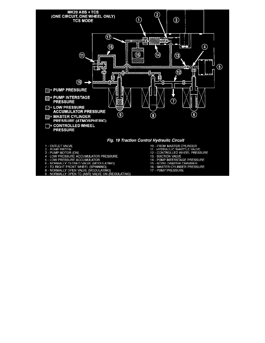
The hydraulic diagram (Fig. 19) shows the vehicle in the Traction Control (TC) mode. The diagram shows a drive wheel is spinning and brake
pressure is required to reduce its speed.
^
The normally open TC (ASR) valve is energized to isolate the brake fluid being pumped from the master cylinder and to isolate the driven wheel.
^
The normally open TC (ASR) valve bypasses the pump output back to the master cylinder at a fixed pressure setting.
^
The normally open and normally closed valves modulate (build/decay) the brake pressure as required to the spinning wheel.