
Sebring Sedan L4-2.4L VIN J (2004)
Powertrain Control Module
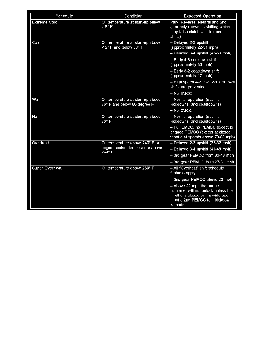
As driving conditions change, the PCM appropriately adjusts the shift schedule. Refer to the following chart to determine the appropriate operation
expected, depending on driving conditions.
SENSOR RETURN - PCM INPUT
The sensor return circuit provides a low electrical noise ground reference for all of the systems sensors. The sensor return circuit connects to internal
ground circuits within the Powertrain Control Module (PCM).
DATABUS COMMUNICATION RECEIVE-PCM INPUT
The PCM uses the SCI communication bus to preform engine diagnostics and flash operations. The transmission side of the PCM uses the SCI
communication bus to flash new software. However, diagnostics is performed via the vehicles J1850 bus for the transmission side of the PCM.
IGNITION SENSE-PCM INPUT
The ignition sense input informs the Powertrain Control Module (PCM) that the ignition switch is in the crank or run position.
PCM REPLACEMENT
USE THE DRB SCAN TOOL TO REPROGRAM THE NEW PCM WITH THE VEHICLES
ORIGINAL IDENTIFICATION NUMBER (VIN) AND THE VEHICLES ORIGINAL MILEAGE. IF THIS STEP IS NOT DONE A DIAGNOSTIC
TROUBLE CODE (DTC) MAY BE SET.