
Sebring Sedan L4-2.4L VIN J (2004)
The PCM adjusts ignition timing based on the following inputs.
-
Inlet Air Temperature
-
Engine Coolant Temperature
-
Engine Speed (crankshaft position sensor)
-
Knock Sensor
-
Manifold Absolute Pressure
-
Park/Neutral (from trans range sensor)
-
Transaxle Gear Engagement
-
Throttle Position
The automatic shut down (ASD) and fuel pump relays are mounted externally, but turned on and off by the powertrain control module.
The camshaft and crankshaft signals are sent to the powertrain control module. If the PCM does not receive both signals within approximately one
second of engine cranking, it deactivates the ASD and fuel pump relays. When these relays are deactivated, power is shut off to the fuel injectors,
ignition coils, fuel pump and the heating element in each oxygen sensor.
The PCM contains a voltage converter that changes battery voltage to a regulated 8.0 volts. The 8.0 volts power the camshaft position sensor, and
crankshaft position sensor. The PCM also provides a regulated 5.0 volts supply for the, manifold absolute pressure sensor, throttle position sensor and
EGR (if equipped).
The PCM engine control strategy prevents reduced idle speeds until after the engine operates for 320 km (200 miles). If the PCM is replaced after 320
km (200 miles) of usage, update the mileage in new PCM. Use the DRBIII(R) scan tool to change the mileage in the PCM.If equipped with SKIM, must
use SKIM function to program VIN number in new PCM.
TRANSMISSION CONTROL
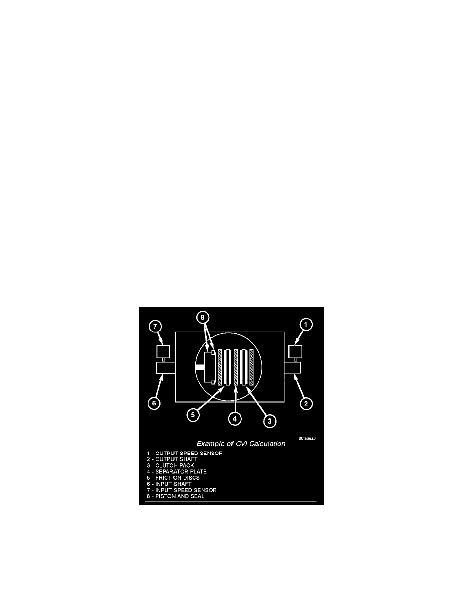
CVI CALCULATION
An important function of the PCM is to monitor Clutch Volume Index (CVI). CVIs represent the volume of fluid needed to compress a clutch pack.
The PCM monitors gear ratio changes by monitoring the Input and Output Speed Sensors. The Input, or Turbine Speed Sensor sends an electrical signal
to the PCM that represents input shaft rpm. The Output Speed Sensor provides the PCM with output shaft speed information.
Example Of CVI Calculation
By comparing the two inputs, the PCM can determine transaxle gear ratio. This is important to the CV1 calculation because the PCM determines CVIs
by monitoring how long it takes for a gear change to occur.
Gear ratios can be determined by using the DRB Scan Tool and reading the Input/Output Speed Sensor values in the "Monitors" display. Gear ratio can
be obtained by dividing the Input Speed Sensor value by the Output Speed Sensor value.