
Sebring Sedan L4-2.4L VIN X (2001)
3. Install the 24-way connector into the socket on the CAB. The connector is installed using the following procedure. Position the 24-way connector
in the socket on the CAB and carefully push it down as far as it will go. When connector is fully seated into the CAB socket push in the connector
lock as far as it will go. This will pull the connector into the socket on the CAB and lock it in the installed position.
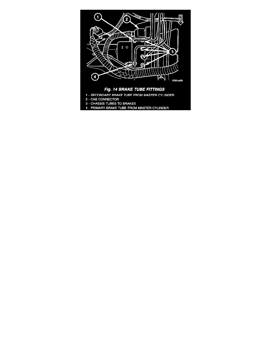
4. Install the four chassis brake tubes (going to each brake) to the top of the ICU. Tighten the tube fittings to 17 Nm (145 inch lbs.) torque with the
aid of a crow foot wrench.
5. Install the two brake tubes coming from the primary and secondary master cylinder ports to the top corners of the ICU. Tighten the tube fittings to
17 Nm (145 inch lbs.) torque with the aid of a crow foot wrench.
6. Install the air cleaner housing..
7. Remove the brake pedal holding tool.
8. Install the remote. ground cable onto the ground stud located on left shock tower.
9. Bleed the base brakes and the ABS brakes hydraulic system.
10. Road test vehicle to ensure proper operation of the base and ABS systems.