
Sebring Sedan L4-2.4L VIN X (2001)
Electrical Accessory Panel: Description and Operation
POWER DISTRIBUTION
This information covers the various standard and optional power distribution components used on this model.
The power distribution system for this vehicle is designed to provide safe, reliable, centralized and convenient to access distribution of the
electrical current required to operate all of the many standard and optional factory-installed electrical and electronic powertrain, chassis, safety,
comfort and convenience systems. At the same time, these systems were designed to provide centralized locations for conducting diagnosis of
faulty circuits, and for sourcing the additional current requirements of many after market vehicle accessory and convenience items.
These power distribution systems also incorporate various types of circuit control and protection features, including:
-
Fuses
-
Fuse cartridges
-
Fusible links
-
Automatic resetting circuit breakers
-
Relays
-
Flashers
-
Timers
-
Circuit splice blocks.
The power distribution system for this vehicle consists of the following components:
-
Power Distribution Center (PDC)
-
Junction Block (JB)
-
Accessory power outlet.
Following are general descriptions of the major components in the power distribution system. Refer to the owner's manual in the vehicle glove box
for more information on the features, use and operation of all of the power distribution system components.
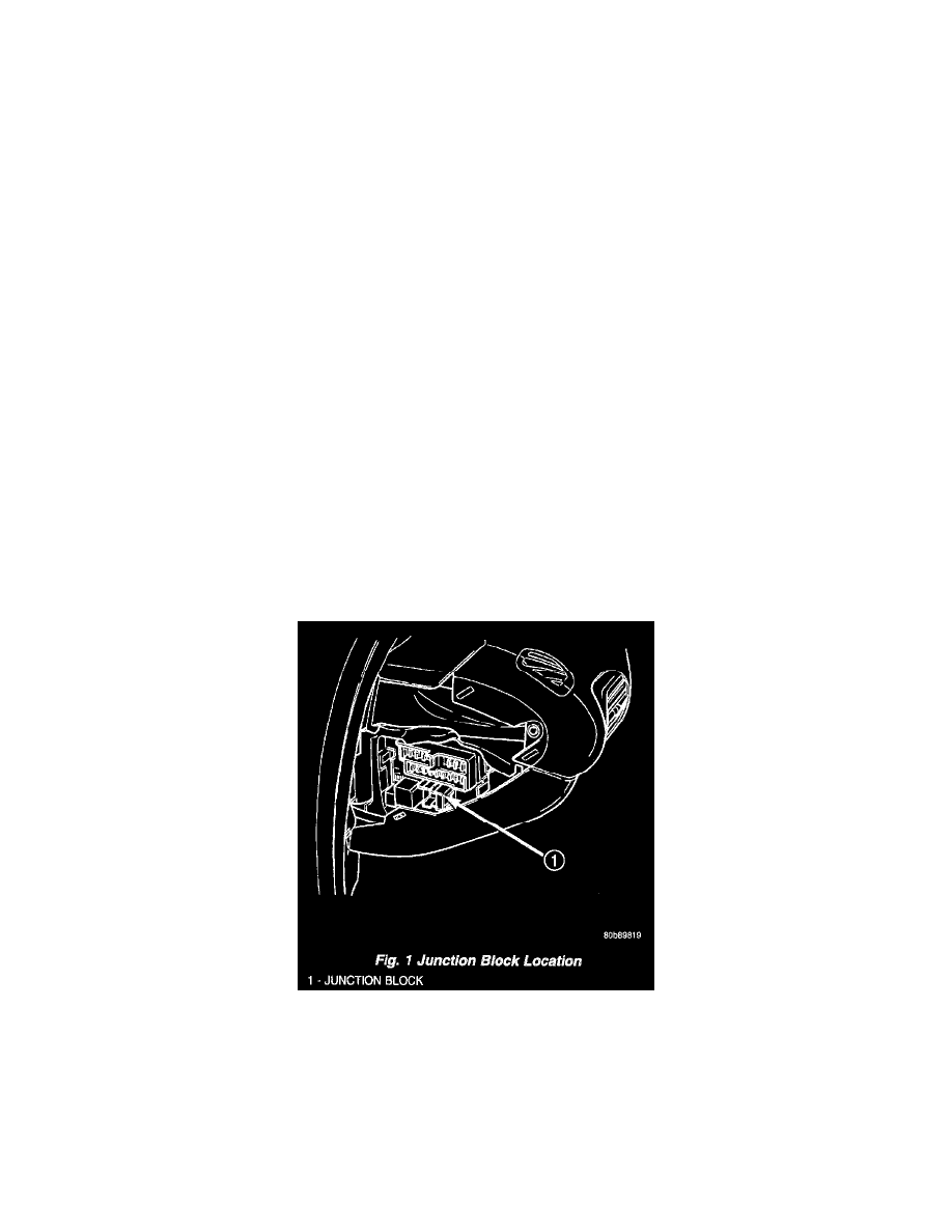
JUNCTION BLOCK
An electrical Junction Block (JB) is located in the left end cap of the instrument panel. The JB combines the functions previously provided by a
separate fuse block module and relay center. It also serves to simplify and centralize numerous electrical components, as well as to distribute
electrical current to many of the accessory systems in the vehicle. It eliminates the need for numerous splice connections and serves in place of a
bulkhead connector between many of the engine compartment, instrument panel, and body wire harnesses.
Fig.1 Junction Block Location
The JB is positioned on a mounting bracket up and under the left instrument panel (Fig. 1). It is secured by three screws. The JB is concealed
behind the left instrument panel endcap. The left instrument panel endcap is a snap-fit fuse access cover that conceals the JB fuses and includes the
fuse layout to ensure proper fuse identification. The left instrument panel endcap must be removed to access components other than the fuses in the
JB.
All of the current entering and leaving the JB does so through wire harnesses, which are connected to the JB through integral connector receptacles
molded into the JB housing. The JB houses blade-type fuses, blade-type automatic resetting circuit breakers, full International Standards
Organization (ISO) relays, and ISO micro-relays. Internal connection of all the JB circuits is accomplished by an intricate network of hard wiring