
Sebring Sedan V6-2.7L VIN R (2004)
Alignment: Service and Repair
Wheel Alignment
STANDARD PROCEDURE - WHEEL ALIGNMENT
1. Position the vehicle on an alignment rack.
2. Perform the PRE-WHEEL ALIGNMENT INSPECTION.
3. Install all required alignment equipment on the vehicle per the alignment equipment manufacturer's instructions. On this vehicle, a four-wheel
alignment is recommended.
NOTE: Prior to reading the vehicle's alignment readouts, the front and rear of vehicle should be jounced. Induce jounce (rear first, then front) by
grasping the center of the bumper and jouncing each end of vehicle an equal number of times. The bumper should always be released when vehicle is
at the bottom of the jounce cycle.
4. Read the vehicle's current front and rear alignment settings. Compare the vehicle's current alignment settings to the vehicle specifications for
camber, caster and toe-in.
NOTE: Set the rear wheel alignment first before proceeding to the front to set the front wheel alignment.
5. If rear camber or toe is not within specifications, proceed to REAR CAMBER AND TOE. If rear camber and toe are within specifications, but
front camber and caster are not, proceed to FRONT CAMBER AND CASTER. If rear camber and toe, and front camber and caster are within
specifications, proceed to FRONT TOE.
Rear Caster on this vehicle is not adjustable and is not shown as an alignment specification.
CAUTION: Do not attempt to adjust the vehicle's wheel alignment by heating, bending or modifying any component of the suspension.
REAR CAMBER AND TOE
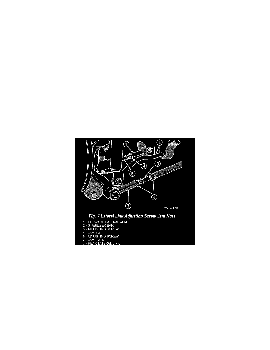
Rear Camber on this vehicle is adjustable. The rear camber on this vehicle is adjusted using the adjusting screw located in the forward and rear lateral
links of the vehicles rear suspension (Fig. 7).
CAUTION: When checking the rear alignment on this vehicle, the alignment rack must be equipped with rear skid plates.
1. For either rear wheel needing alignment, loosen the adjusting screw jam nuts (Fig. 7) on both the front and the rear liters links.
CAUTION: Do not attempt to move the adjusting screws without properly loosening the jam nuts. Note that each adjusting screw has one
right-handed nut and one left-handed nut.