
Sebring Sedan V6-2.7L VIN R (2004)
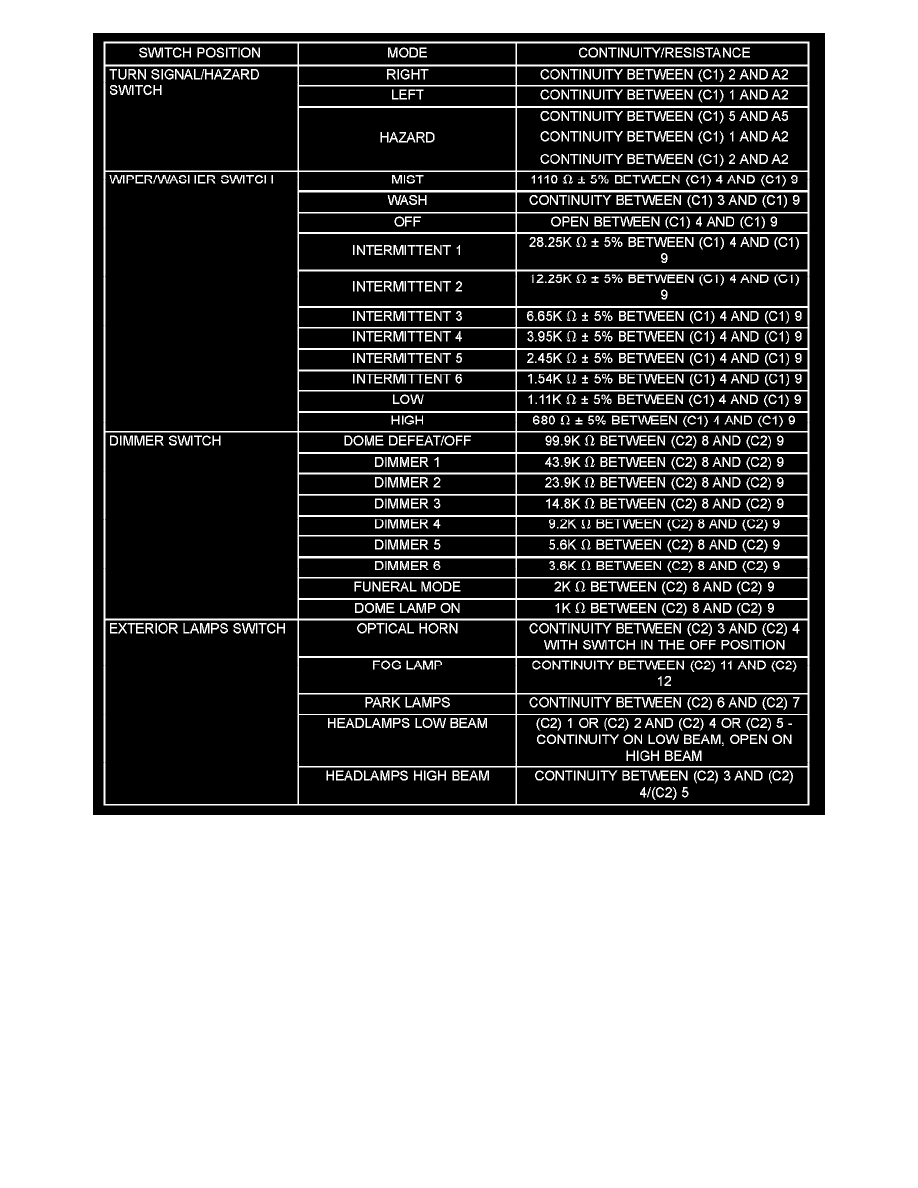
Multi - Function Switch Continuity /resistance
2. Using an ohmmeter, test for continuity/resistance between the terminals of the switch as shown in the MULTI-FUNCTION SWITCH
CONTINUITY/ RESISTANCE table. Refer to Wiring Diagrams for C1 and C2 connector pin-outs. Refer combination flasher (A) pin-outs.
The switch assembly is mounted over the center of the steering column under the steering column shrouds. Should any function of the switch fail, the
entire switch assembly must be replaced.