
Sebring Sedan V6-2.7L VIN T FFV (2003)
NOTE:
-
The connecting rod bearing cap bolts must be examined before reuse. If the threads are necked down due to stretching, the bolt(s) must be
replaced (Fig. 51).
-
Connecting rod bolts are retained in the rod cap with a light press fit. If bolts are to be removed, use a hammer and punch to drive bolts from
connecting rod cap using care not to damage fractured cap surface.
1. Examine connecting rod bolt for stretching. Stretching can be checked by holding a scale or straight edge against the threads. If all the threads do
not contact the scale the bolt should be replaced.
2. Before installing the bolts, lubricate the threads with engine oil.
3. Install bolts finger tight. Then alternately torque each nut to assemble the cap properly.
4. Tighten the nuts to specification.
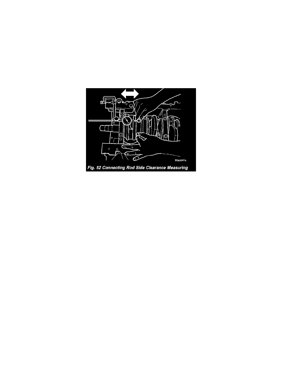
CONNECTING ROD SIDE CLEARANCE
1. Mount a dial indicator to a stationary point on engine. Locate probe perpendicular to and resting against the connecting rod cap being checked.
Move connecting rod all the way to rear of its travel. Zero the dial indicator. Move connecting rod forward to limit of travel and read the dial
indicator (Fig. 52). Compare measurement to specification listed in engine specifications. Repeat procedure for each connecting rod. Turn
crankshaft for connecting rod accessibility.