
TC BY Maserati V6-181 2972cc 3.0L SOHC VIN S FI (1991)
Hydraulic Control Assembly - Antilock Brakes: Description and Operation
The Hydraulic Assembly
The hydraulic assembly will be discussed as three separate components and then as a whole. The first portion of the assembly to be discussed is
the pump/motor assembly. This is a piston type pump driven by an electric motor. The pressure from the pump is delivered to the accumulator
where it is stored for use by the booster. The accumulator is a two chamber device with one chamber charged with nitrogen and the other for the
brake fluid. The chambers are separated by a rubber bladder which acts as a piston to deliver the needed fluid to the booster and rear brakes.
Pressure is controlled by the pressure switch, a combination pressure and warning switch. The pressure switch is located on the pump assembly
and is identified by its five pin connector. This assembly has essentially three switches operated by a single piston. The first switch is for pressure
maintenance in the accumulator which is kept at a level between 1885-2755 psi. The second switch is a normally closed switch which is directly
connected to the red BRAKE warning lamp on the dash. And the last is a normally open switch which is used by the controller to indicate that
enough pressure is in the accumulator for normal ABS operation. In the event of loss of sufficient pressure to operate the ABS system, the red
BRAKE warning lamp and the amber ANTI-LOCK warning lamp will illuminate. This warning will occur at 1524 psi.
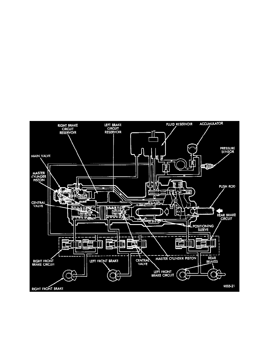
The second assembly in the hydraulic assembly is the booster with tandem master cylinder. When the brake pedal is depressed, high pressure fluid
from the accumulator is ported through a small spool valve and into the boost chamber. The pressure in the chamber is regulated by the spool to
maintain a pressure proportional to the pedal force applied by the driver. The fluid is also delivered from the boost chamber to the rear brakes. The
master cylinder is a tandem type, with separate circuits for the front right and left brakes. Also part of the master cylinder booster assembly is the
main valve. This valve is located in the front of the master cylinder and is identified by the two pin connector. The function of this valve is to refill
the master cylinder and reset the pedal to thirty percent of travel during the anti-lock modulated. stop. This is accomplished by porting high
pressure fluid into the master cylinder and into a resetting piston. This is responsible for the pulsating pedal during the anti-lock modulated stop.
The third assembly is the valve block that is attached to the master cylinder. The valve block controls the pressure to the wheel circuits in the
anti-lock mode. Consisting of six solenoid valves, the valve block controls circuit pressure by either blocking or releasing fluid from the wheel
circuits. Each wheel circuit has a pair of valves, one normally open (NO) and the other is a normally closed (NC). In the normal operation without
anti-lock, fluid from the master cylinder is ported through the NO valve to the proper wheel circuit. During anti-lock, the valve block works in
three phases. These phases are the pressure holding, reducing and increasing. While in the pressure holding phase, the normally open valve is
closed so that no additional pressure can enter the system through the master cylinder. In the pressure reduction phase, the NO valve closes and the
NC valve is pulsed so that pressure can be removed from the circuit and the fluid returned to the reservoir. Pressure increase is achieved by pulsing
open the already closed NO valve.