
Town & Country V6-3.3L VIN R (2003)
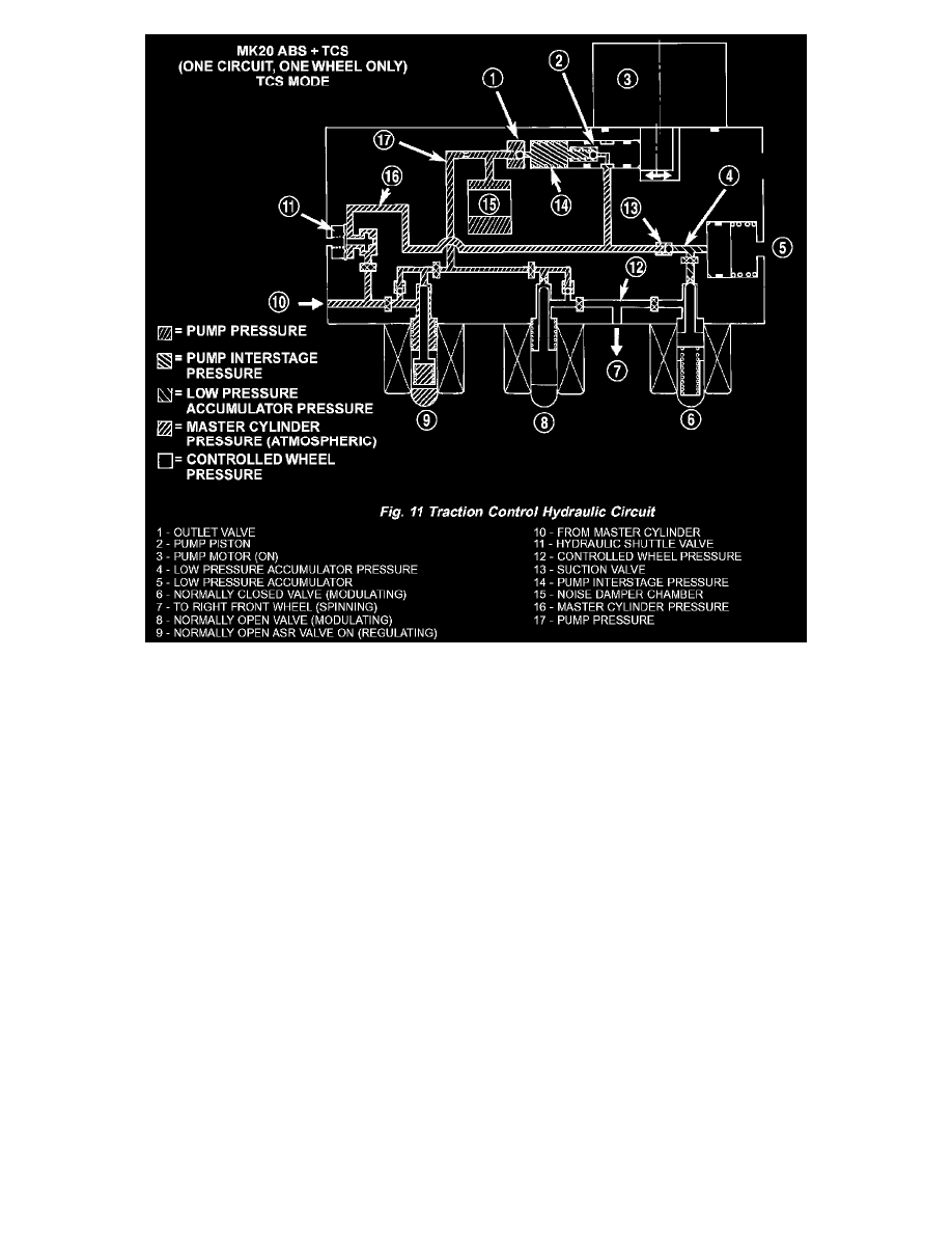
The hydraulic diagram shows the vehicle in the ABS braking mode. The diagram shows a drive wheel is spinning and brake pressure is required to
reduce its speed.
^
The normally open ASR valve is energized to isolate the brake fluid being pumped from the master cylinder and to isolate the driven wheel.
^
The normally open ASR valve bypasses the pump output back to the master cylinder at a fixed pressure setting.
^
The normally open and normally closed valves modulate (build/decay) the brake pressure as required to the spinning wheel.