
Town & Country V6-3.3L VIN R (2003)
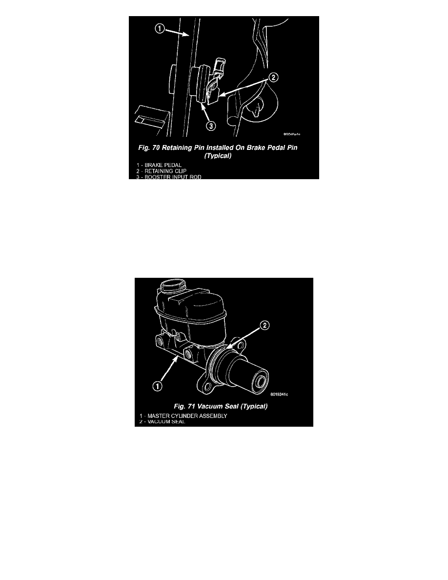
4. Install booster input rod on brake pedal torque shaft pin and install a NEW retaining clip.
5. Install booster input rod trim cover.
6. Connect vacuum hose to check valve on power brake booster.
CAUTION: The master cylinder (and its rear seal) is used to create the seal for holding vacuum in the vacuum booster. The vacuum seal on the
master cylinder MUST be replaced with a NEW seal whenever the master cylinder is removed from the vacuum booster.
CAUTION: When removing the vacuum seal from the master cylinder, do not use a sharp tool.
7. Using a soft tool such as a trim stick, remove the vacuum seal from the master cylinder mounting flange.
8. Install a NEW vacuum seal on rear mounting flange of the master cylinder.
9. Position master cylinder on studs of booster, aligning push rod on booster with master cylinder piston.
10. Install the two nuts mounting the master cylinder to the booster. Tighten both mounting nuts to a torque of 25 Nm (225 in. lbs.).
11. Connect wiring harness connector to brake fluid level switch in the master cylinder fluid reservoir.
12. If the vehicle is equipped with the 2.5L diesel engine, install the coolant recovery pressure container and bracket.
13. If equipped with speed control, install speed control servo and connect wiring connector. Tighten the mounting nuts to a torque of 14 Nm (124 in.
lbs.).
14. Install the battery tray. Install the two nuts and one bolt attaching the battery tray to the vehicle. Tighten the bolt and nuts to a torque of 14 Nm
(124 in. lbs.).
15. If vehicle is equipped with speed control, connect the servo vacuum hose to the vacuum tank on the battery tray.
16. Install the battery, clamp and mounting nut.
17. Install the positive battery cable on the battery.
18. Install the negative battery cable on the battery.
19. Install the battery thermal guard shield.